

Almost every user of the AUTOCAD program in drawing up a complex drawing faces the need for its design and layouts into a suitable view. This is done in the "Sheet" module on the specimen. By default, one main species screen is present in one sheet, located on all the workspace. Because of this, sometimes there is the need to create additional screens for placing certain elements of the drawings on them. As part of today's article, we clearly want to demonstrate the interaction procedure with this feature on the example of step-by-step instructions.
We use view screens in AutoCAD
The whole essence of the use of species screens is to create, edit and placing certain parts of the drawing. It is possible to deal with this in just a few minutes, having mastered the main management tools that we want to demonstrate today. The format of the material will be presented in the form of a step-by-step instruction - this will help maximizely consider every aspect of today's task.Step 1: Creating additional species screens
Let's start with the most important goal - the creation of additional species screens. On one sheet there may be an unlimited number of diverse forms. The basic condition consists only that all the necessary elements are fit there and their mapping was correct.
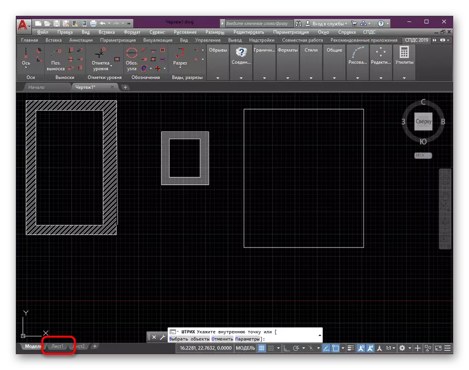
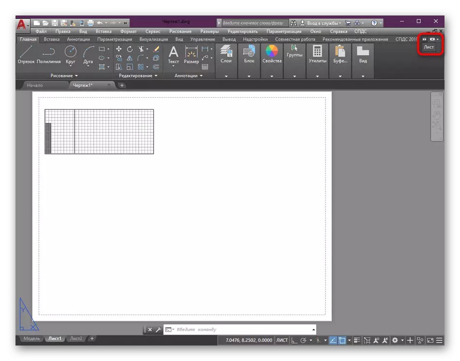
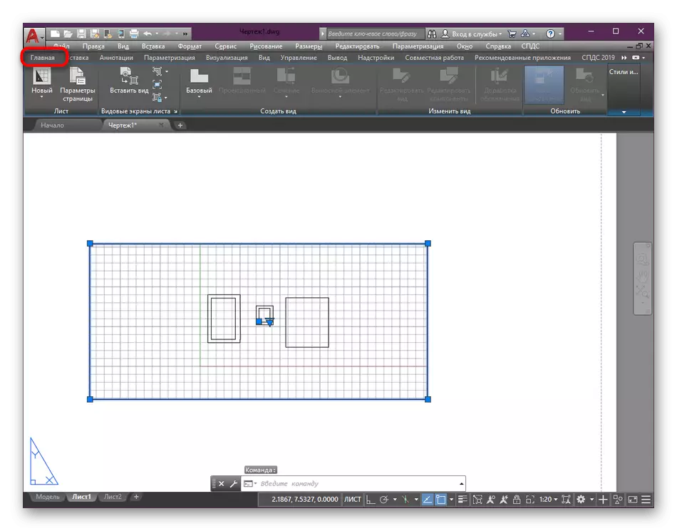
- From the Model module, move to the required sheet by clicking on the special tab at the bottom of the window.
- Here, click on the main mouse screen screen to activate it.
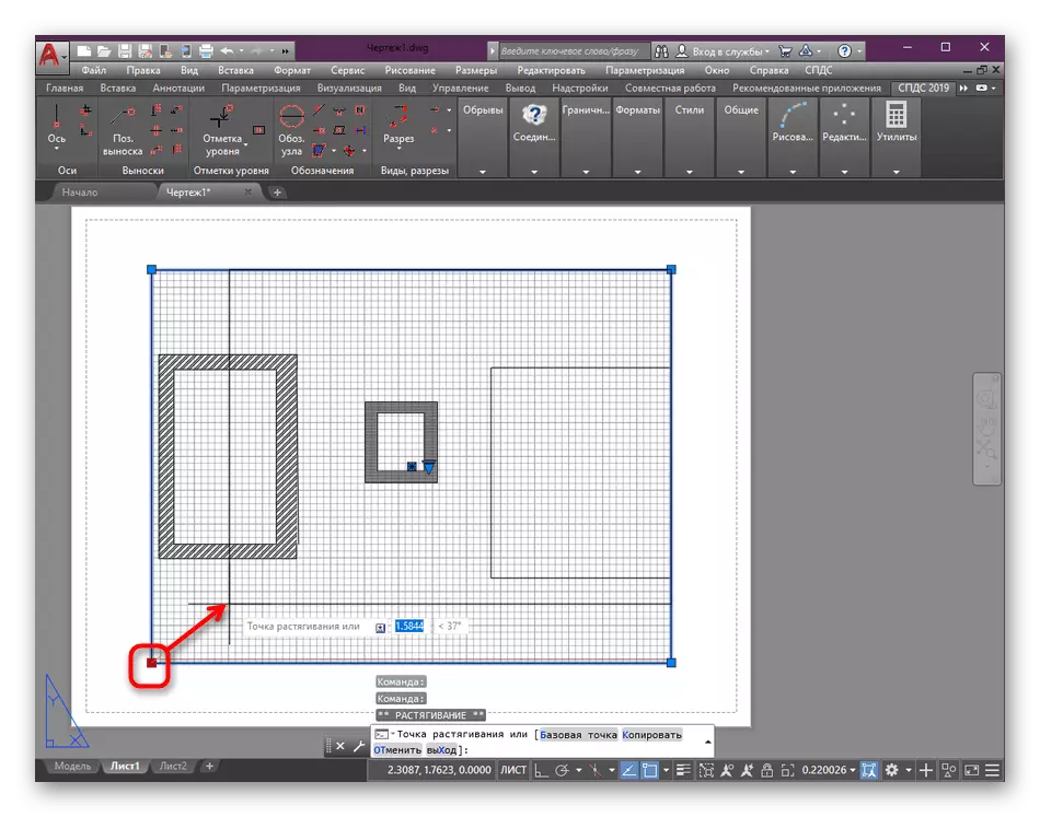
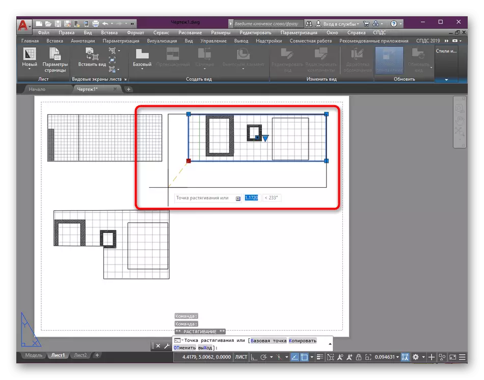
- After the frameworks are marked in blue, you can squeeze the window, freeing the place for other elements. You just need to pull over any basic point.
- Now hold down the LKM on one of the segments and move the window to any place on the canvas to select a convenient location.
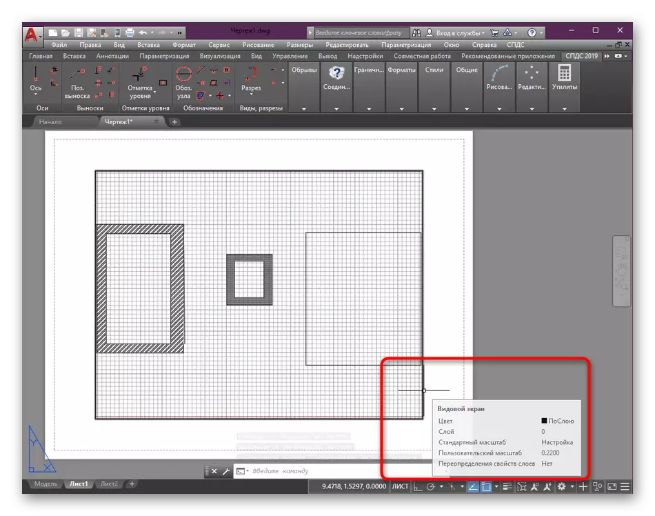
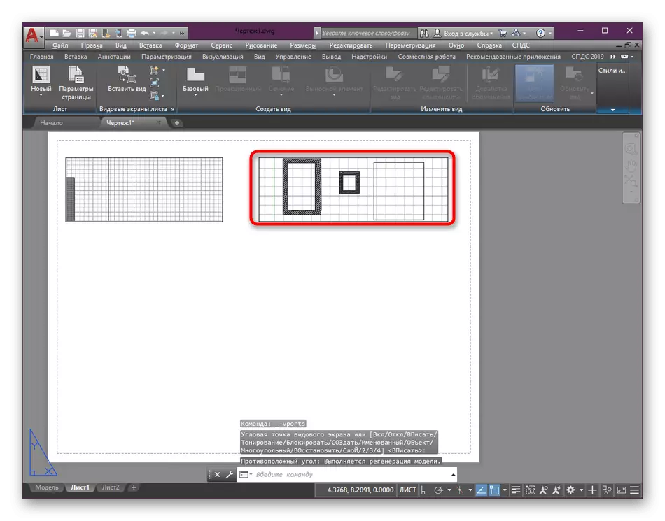
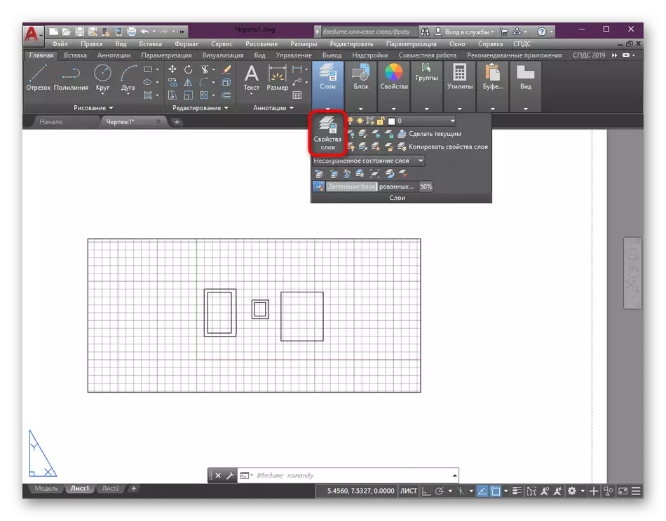
- Pay attention to the tape. Here you need to choose the last section called "Sheet". If you do not work in full-screen mode or the monitor resolution does not allow you to fit all the elements of the tape, press the double arrow at the end of the line to expand all parameters. There already choose the appropriate section.
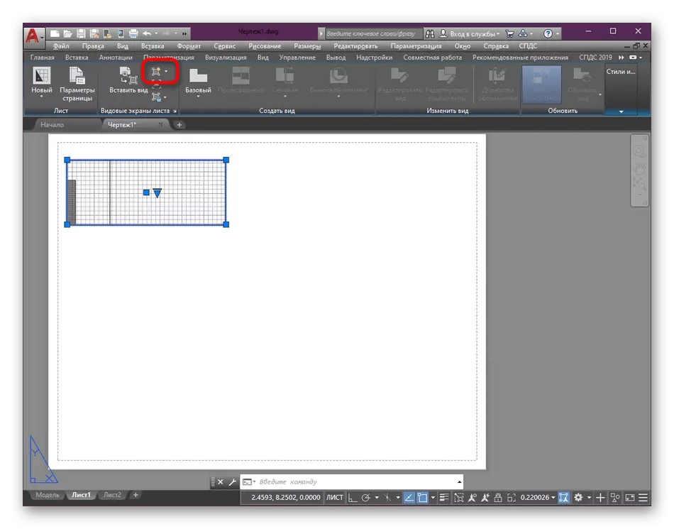
- In the category "Leaf Screens", click on the first button, which has the appropriate icon indicating the addition of a new item.
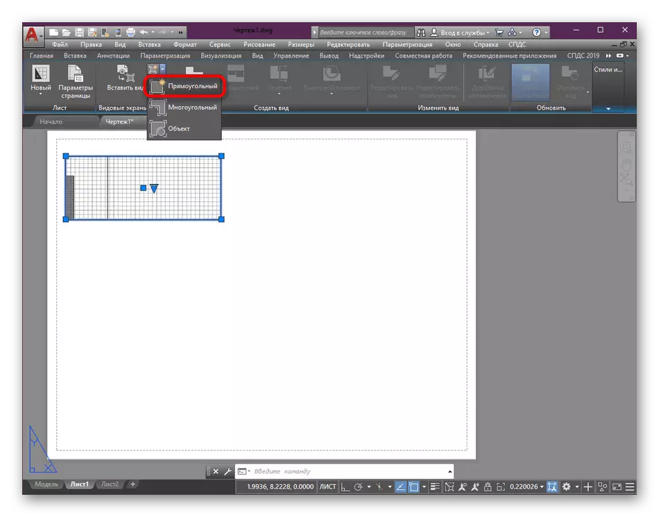
- Here, two options for the drawing area are offered. Let's first choose the frequently used "rectangular" mode.
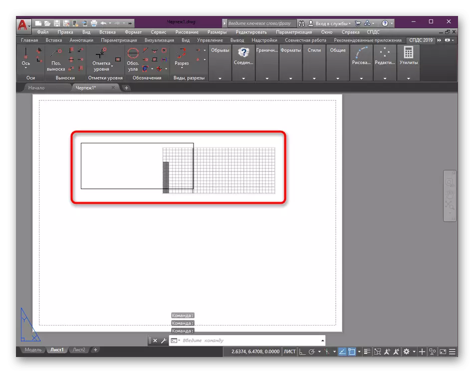
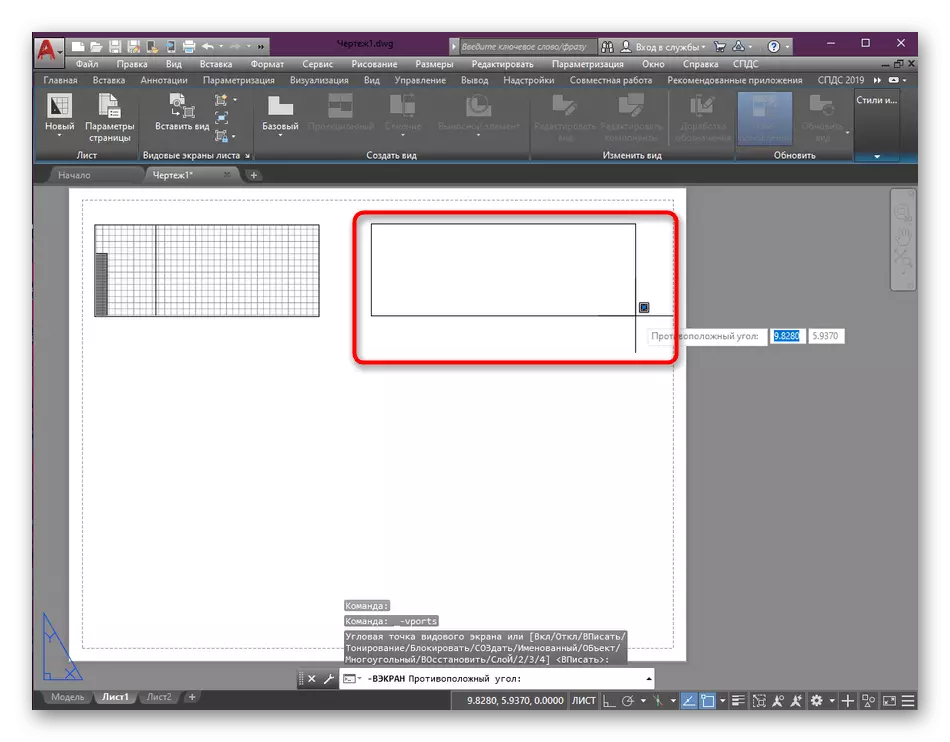
- Using the cursor you only need to set a rectangle of a certain size, then click on the LCM to apply the action.
- After that, the elements of the drawing will be placed in the area. If required, clamp the mouse and Lxcule button at the same time and center the image within the area.
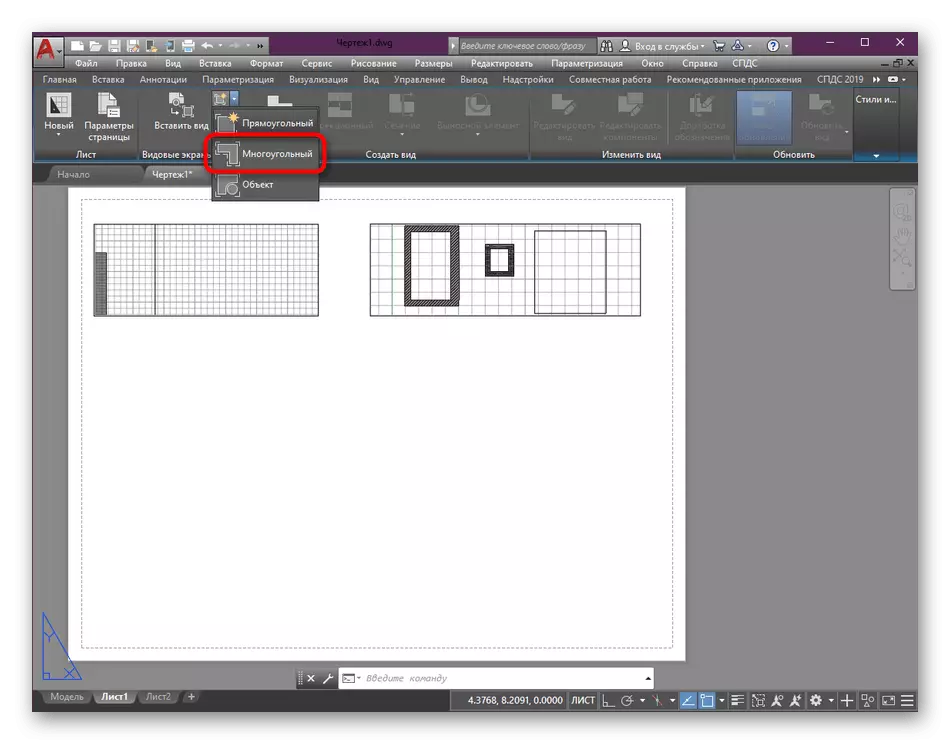
- Create an additional third area consisting of an arbitrary polyline. To do this, in the already familiar menu, select the "Polygonal" mode.
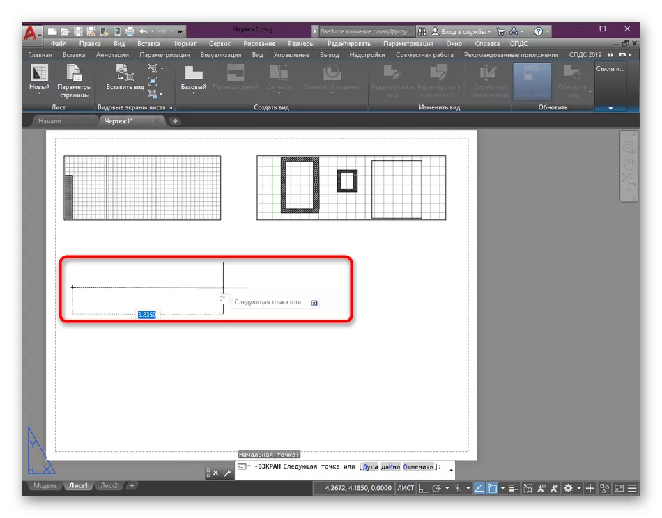
- Start drawing the first line by adding the mouse to the left click.
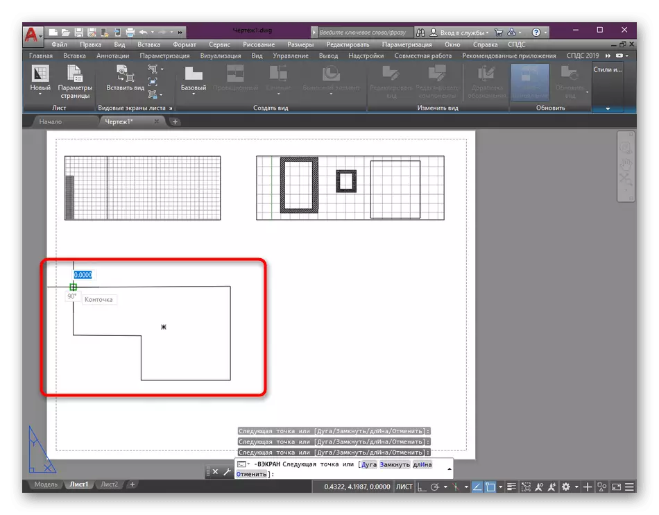
- When you finish, check the end point and press ENTER or space.
- Now you see that the species screen of a specific format has been added. It can also be edited in every way, change in size, scale, what will be discussed.
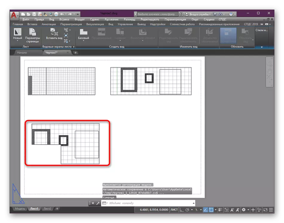
In the same way, an absolutely any number of species screens on one sheet is created. At the same time, the main thing is only competently position them and display inside the drawing elements to get the most beautiful design.
Step 2: Editing View Screens
We smoothly go to the second most important aspect - editing available species screens, because it is not always a standard location, the size and scale of the elements are satisfied with the user. Now we will only touch on the basic parameters that edit most often.
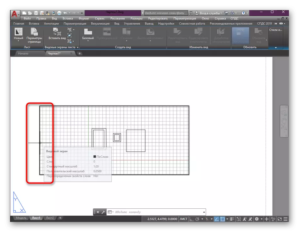
- To begin with, once again we repeat that the size editing occurs by clamping the LKM on one of the base points and movement in the desired direction. This can be done by entering the scale into the corresponding field that appears after the selection of the stretching tool.
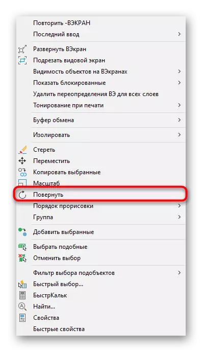
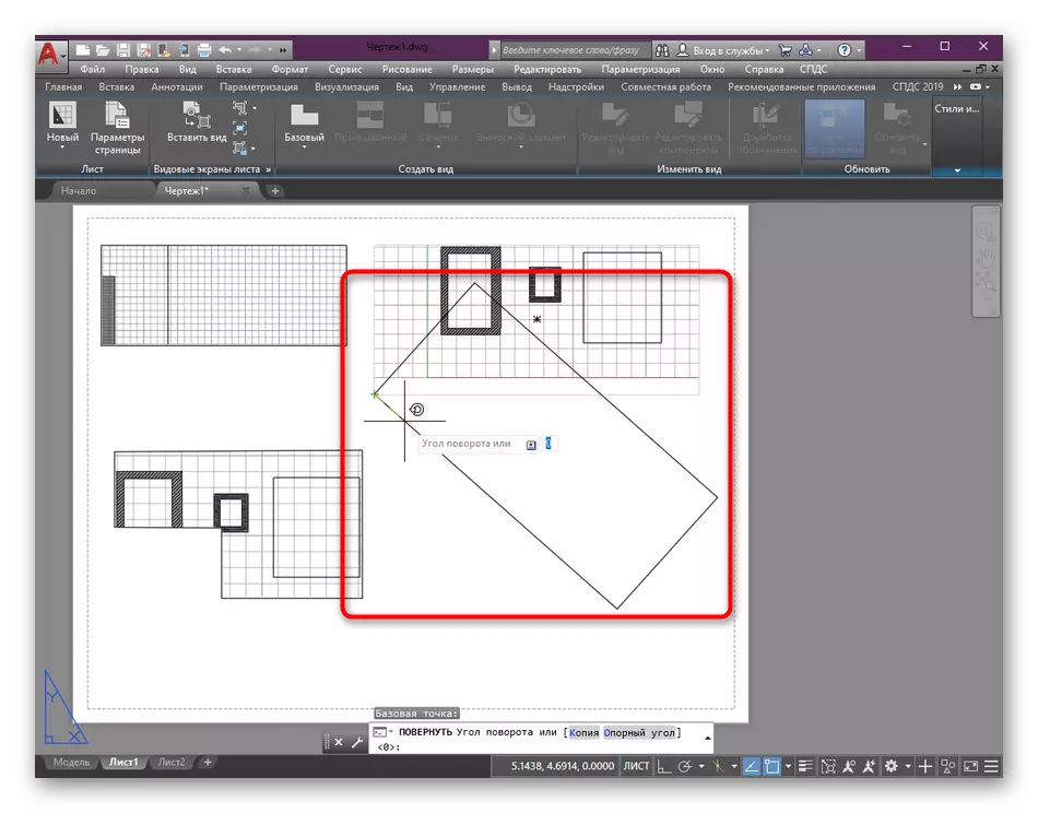
- If you want to rotate the species screen in any position, select it, and then right-click. In the context menu that opens, specify the "Rotate" item.
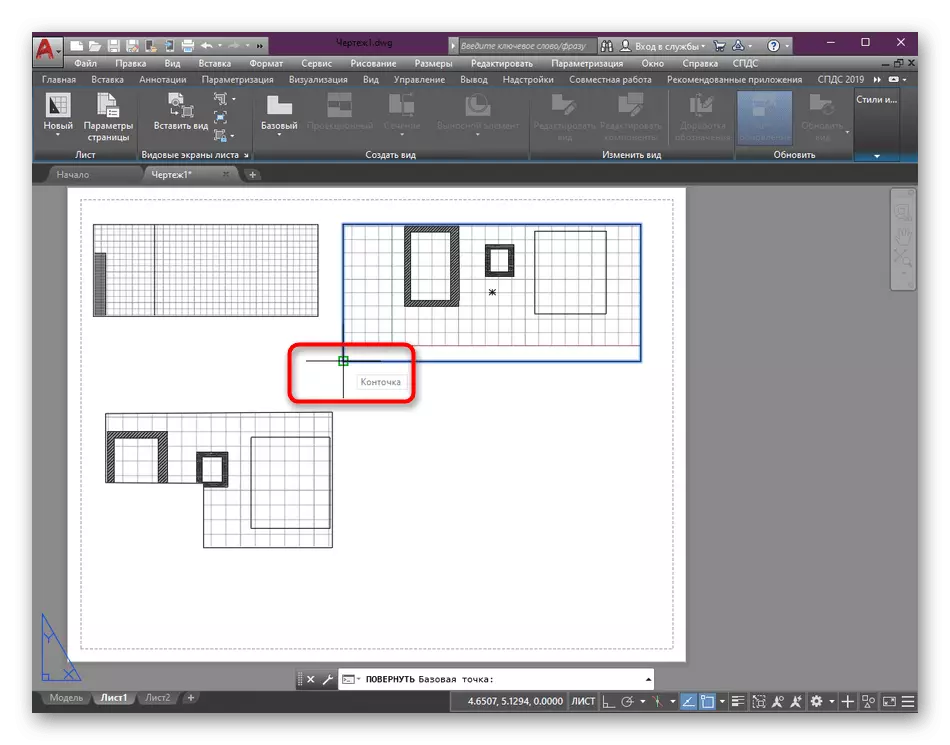
- Select one of the base points that will remain fixed when you turn.
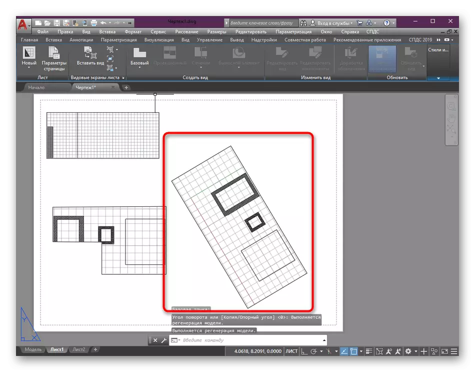
- Specify in the row the required number of degrees in the plus or minus value or delete the screen yourself in one of the directions.
- It should be borne in mind that the elements of the drawing will also be in an inverted state.
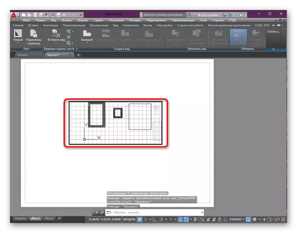
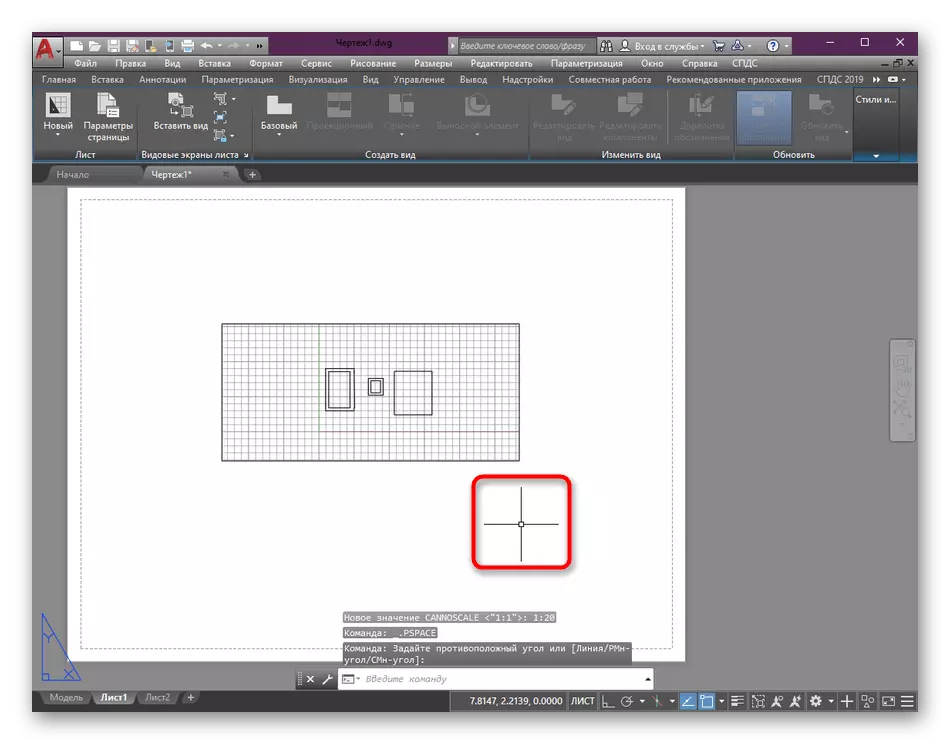
- Sometimes you need to move the area of the drawing falling into the species screen. For this, double-click inside it with LKM, so that the borders become black.
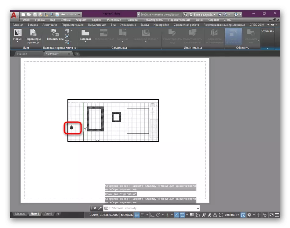
- Using a squeezed mouse wheel button and LKM, move the web in the desired direction.
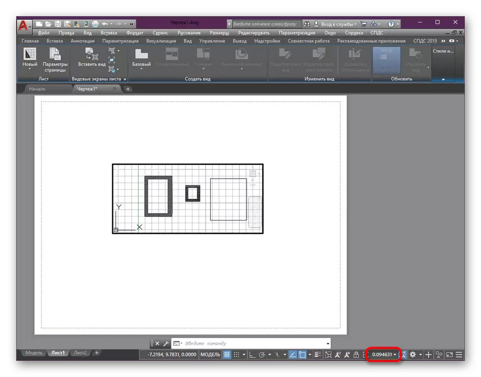
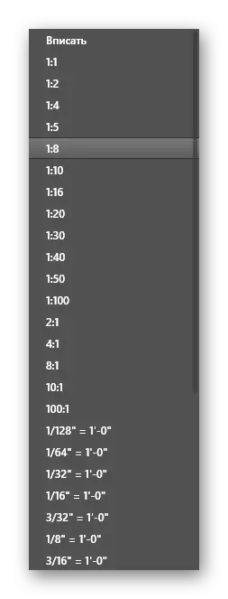
- The last we will affect the change in scale, which is carried out very simply. At the bottom of the statistical panel there is a separate button that displays the scale - click on it to go to edit.
- In the list that opens, select the appropriate value and the change will immediately take effect.
- If you want to exit the viewpoint, simply click on the empty area of the sheet twice the LX to cancel the selection of all items.
With the rest of the settings that appear in the context menu after pressing the PCM by block, even the novice user will look. However, we also want to note that you can create any number of new sheets for placing unique species screens or add frames on them when drawing up drawings. More detailed information about all this you will learn in some of our articles, while moving below the links below.
Read more:
Creating sheets in AutoCAD
Adding and adjusting the frame in AutoCAD
Step 3: Setting up the print screens
We separately transferred the procedures for printing the frameworks of viewports, because newcomers are often faced and wondered about the stroke shutdown when the sheets are shown. Of course, it is impossible to single button immediately turn off the frames from entering the printed list, but the task is not so difficult.
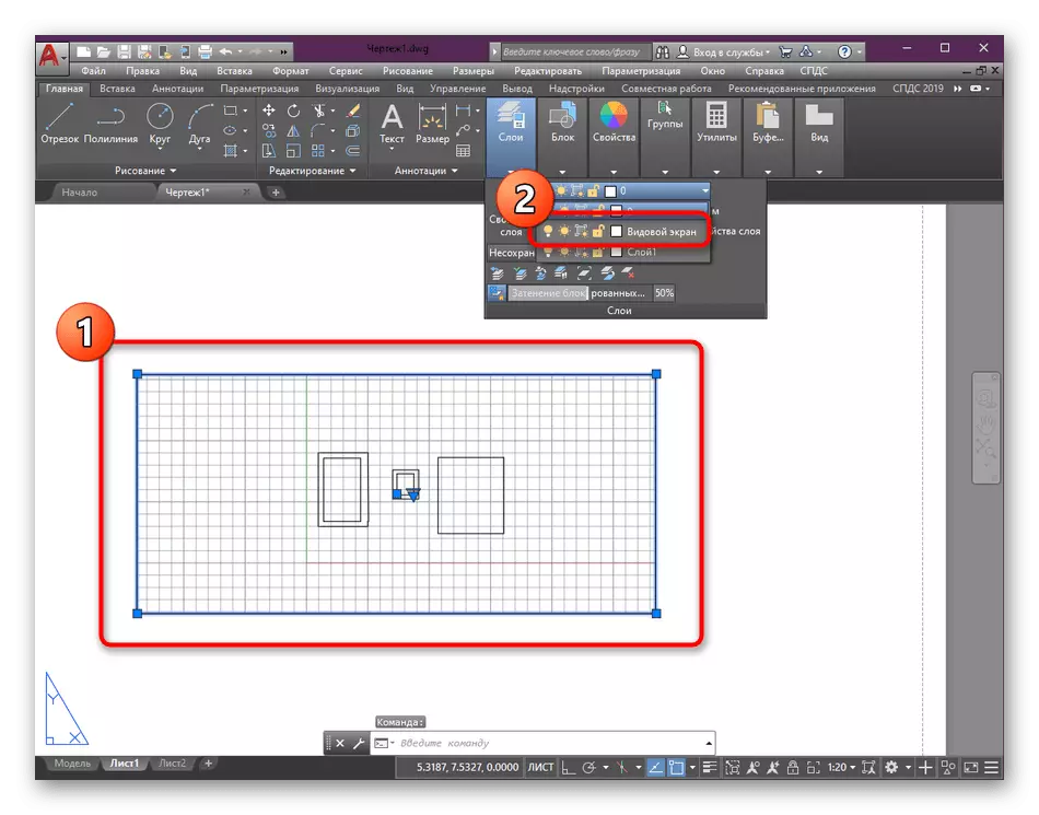
- Highlight the species screen frame by making a single click of the LKM on it.
- The frame itself must be highlighted in blue. Then over the tape, open the "Home" section.
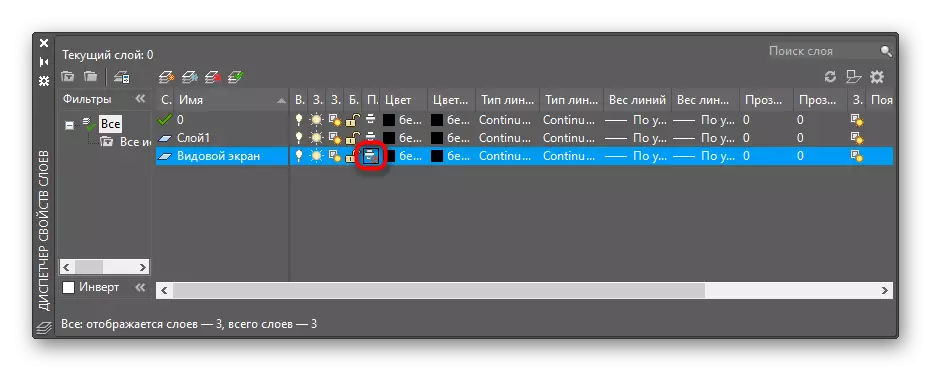
- There, in the category "Layers", place the frame in the empty layer, and if it is missing, go to the "Layer Properties" panel.
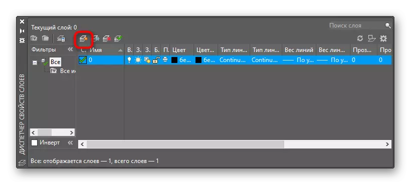
- Create a new layer by clicking on the corresponding button.
- Specify it an arbitrary name and save the changes.
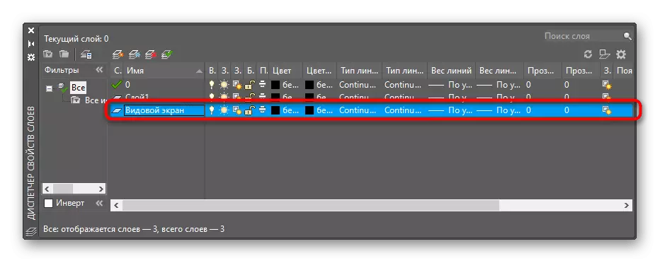
- In the "Print" section, in the settings of this layer, you will need to change the icon to the one where the crossed red circle is displayed near the printer. This will designate that the layer is visible, but it is not displayed.
- After that, re-select the layer of the frame and place it in the same layer.
As part of today's material, we described in detail the main aspects of interaction with the species screens. As you can see, there is no information that refers to this topic is only partially, for example, additional settings for models and other objects. You can read about all this in a separate learning lesson where information is collected about all the most important tools and functions.
Read more: Using AutoCAD Program