

Many users of various graphic editors and similar programs are accustomed to see among the standard dialing of figures and arrow. However, AutoCAD owners in this regard are limited. The functionality of this software does not allow you to create an arrow of any form using just one click on the mouse to the reserved button. Therefore, users faced with the need to draw this item on their own. This can be done in different ways, and we want to consider in detail each of them.
Create an arrow in AutoCAD
Disassembled Further drawing methods imply the use of base instruments of autocard. We will touch on the polyline and ordinary segments, as well as let's talk about how to dismember and create blocks from finished objects. You will only have to choose the most suitable method and produce it, following the instructions below.Method 1: manual drawing arrow by segments
The first option is the most difficult because it requires more time and strength than everyone else. However, its advantage is that you are not limited to any framework. The arrow may be any shape and size, consist of a certain number of segments and additional parts. Let's analyze the simplest example of this purpose.
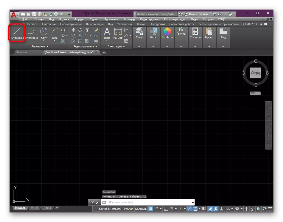
- Run AutoCAD and in the "Drawing" section on the main tape, click on the "Cut" tool.
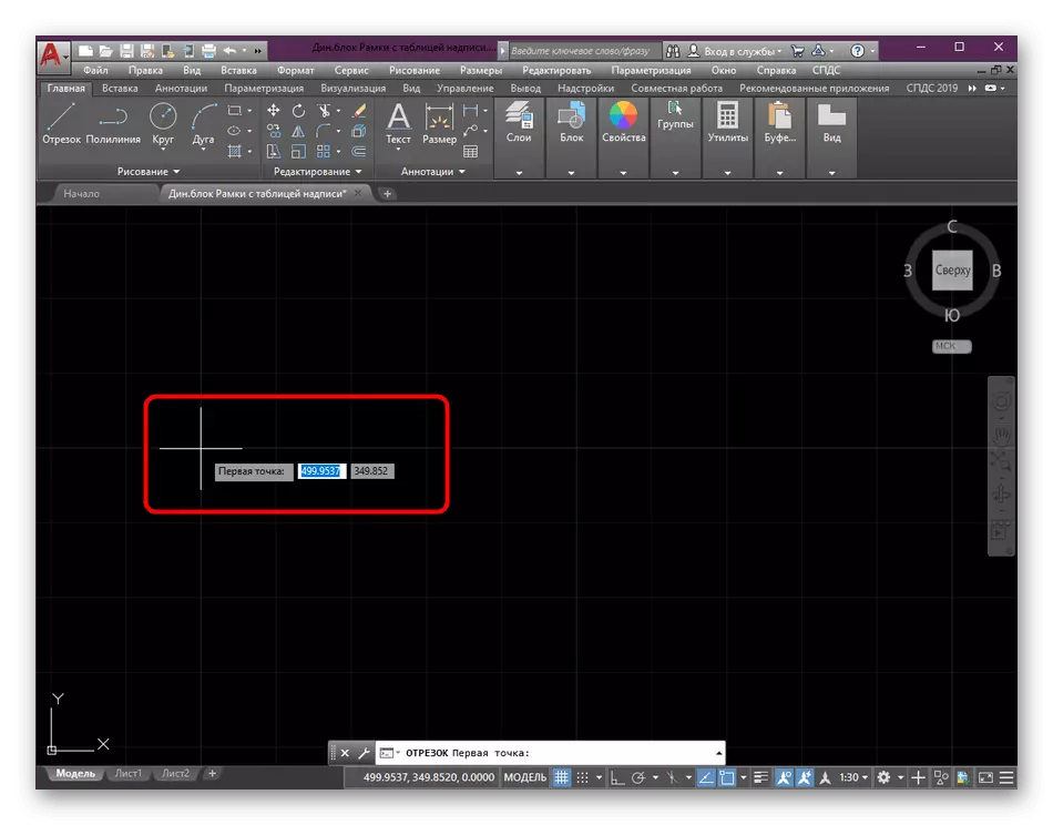
- Start drawing by setting the first point.
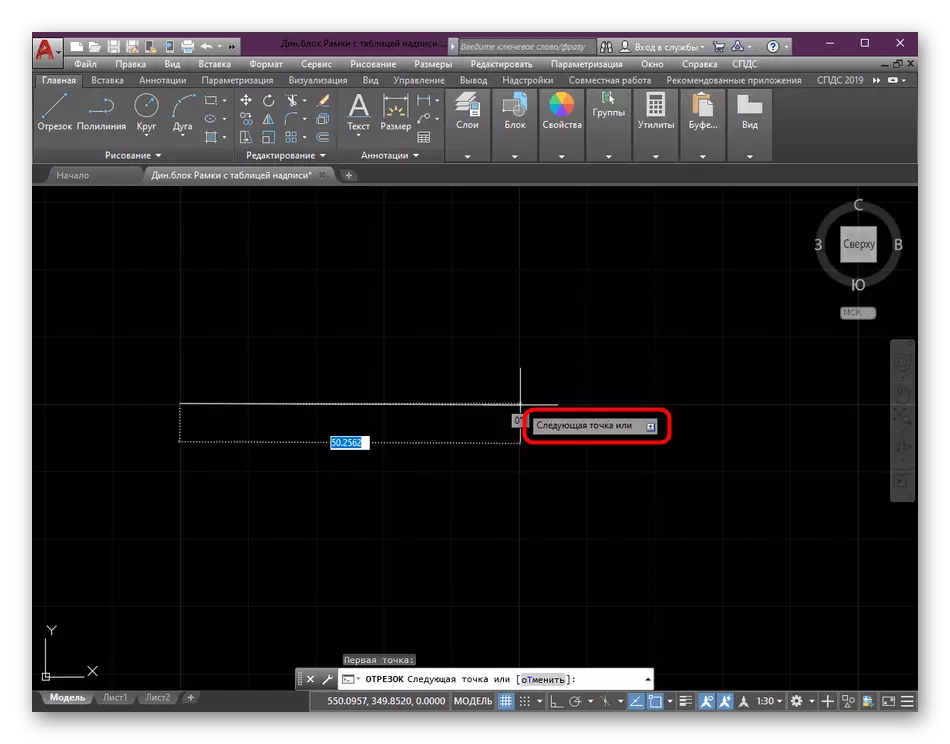
- Spend a straight or curved line, which will continue the base of the arrow.
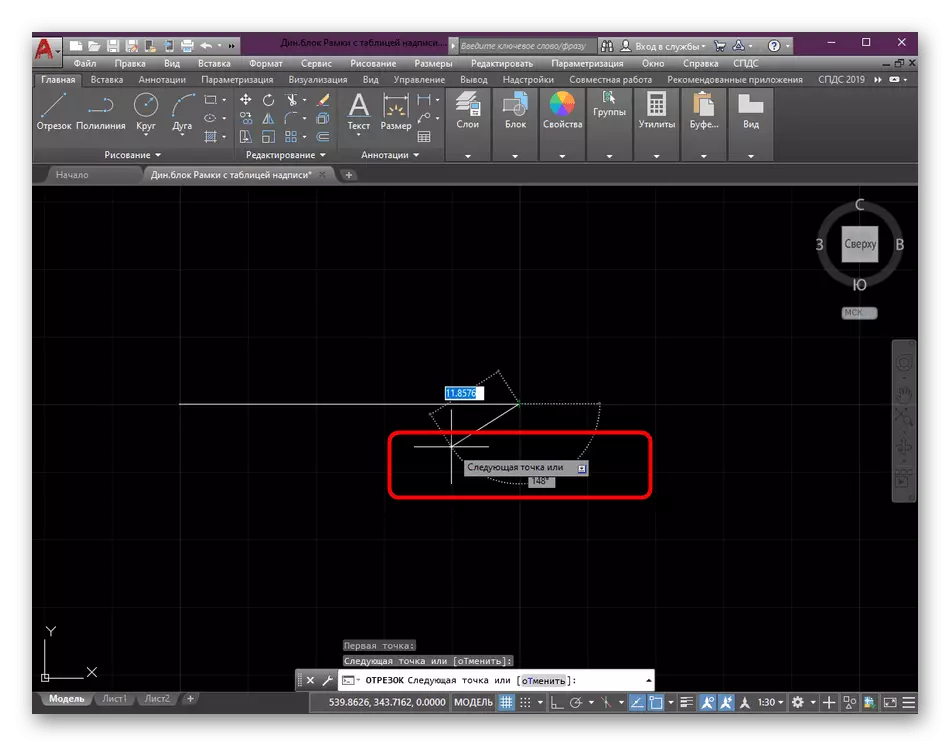
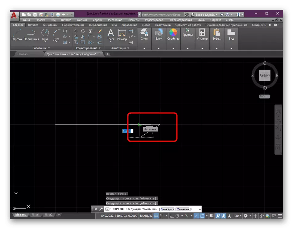
- Next, start forming one of the sides, lowering the line up or down.
- Complete the formation of the side by connecting the base with the center.
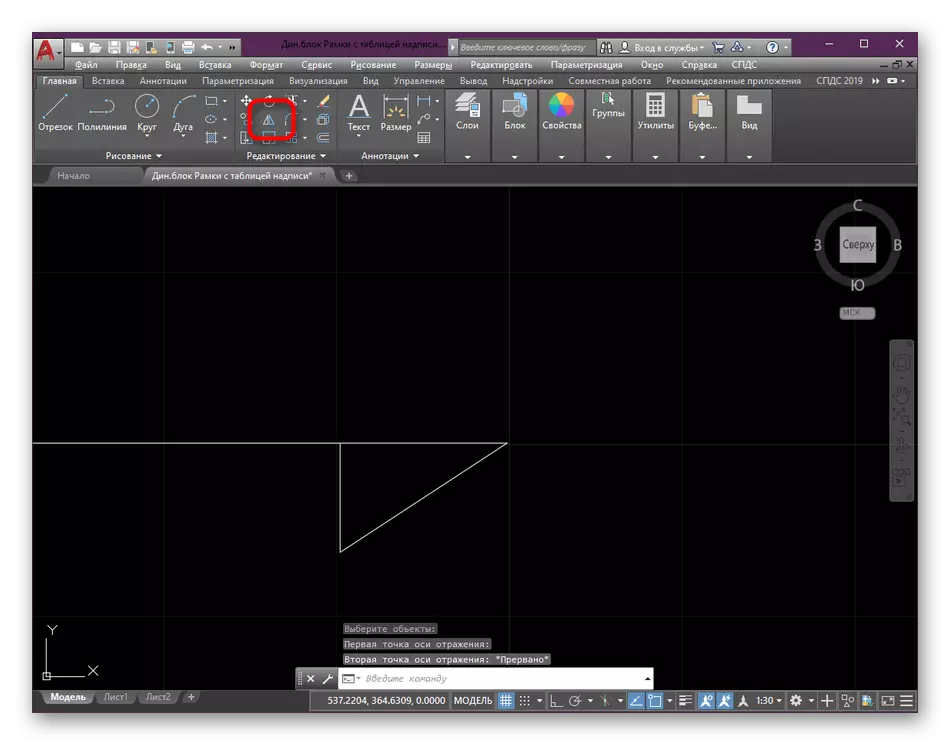
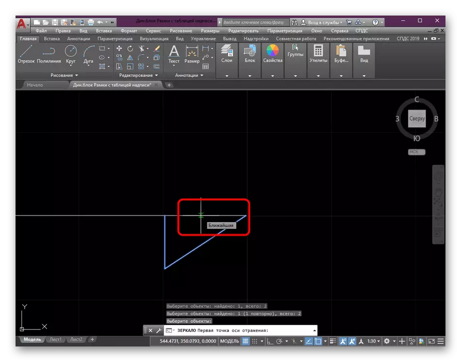
- Now let's talk about how to make exactly the same base and on the other hand to get a smooth arrow. To do this, we will use the standard "Mirror" tool, which is in the Editing section.
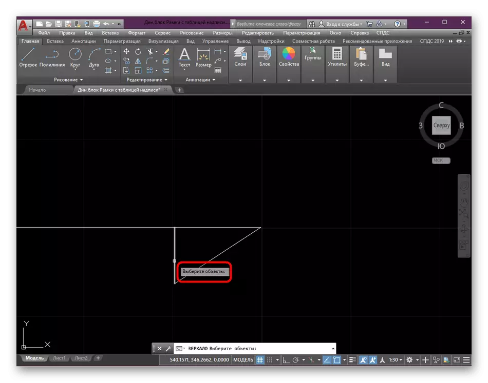
- After selecting this feature, you must specify the objects that will be cut. In our case, these are lines under the centered segment.
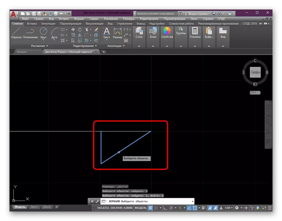
- All selected segments will be highlighted in blue. You need to click on the ENTER key.
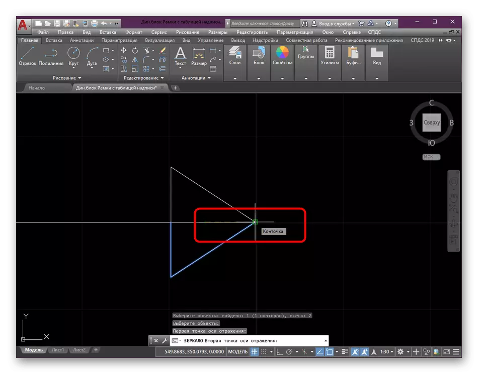
- Specify the line that will perform a focusing reference. Now it is the central segment.
- Compare the point of new segments from the end point of the arrow to get the perfect result.
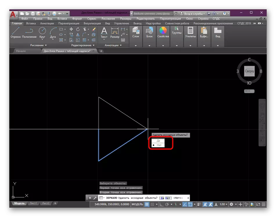
- When you appear the "Delete source objects" inscriptions, select No. If you specify "yes", then the earlier elements of the arrow will simply disappear and everything will need to mirror again.
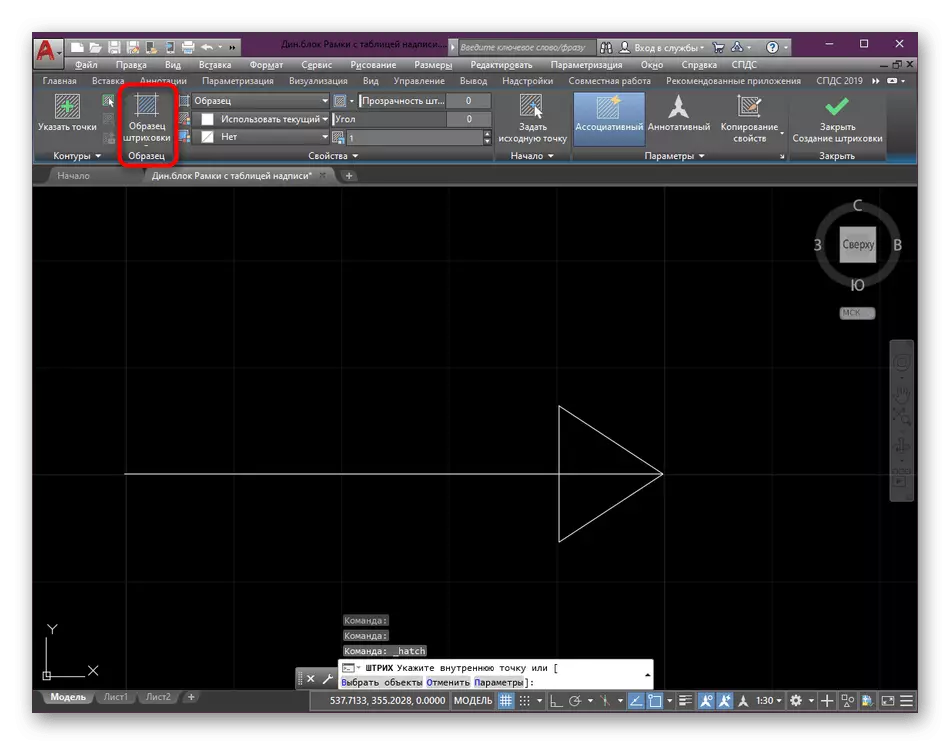
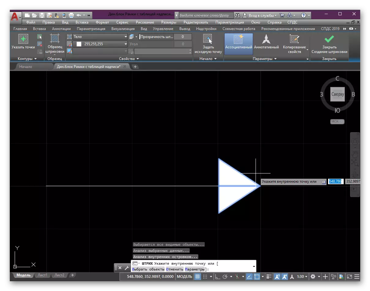
- If you want, you can leave the arrow transparent at the base, however it looks best when the fill is made. In this, the hatching tool will help, because activate it by clicking on the corresponding button in the "Drawing" section.
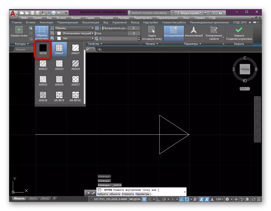
- Expand the list called "Shark Sample".
- Specify the "Solid" option. It is used for filling in color.
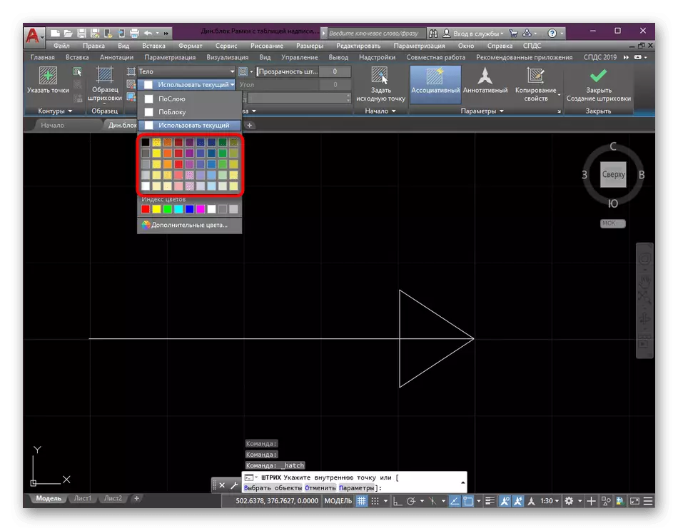
- It remains only to choose the appropriate color.
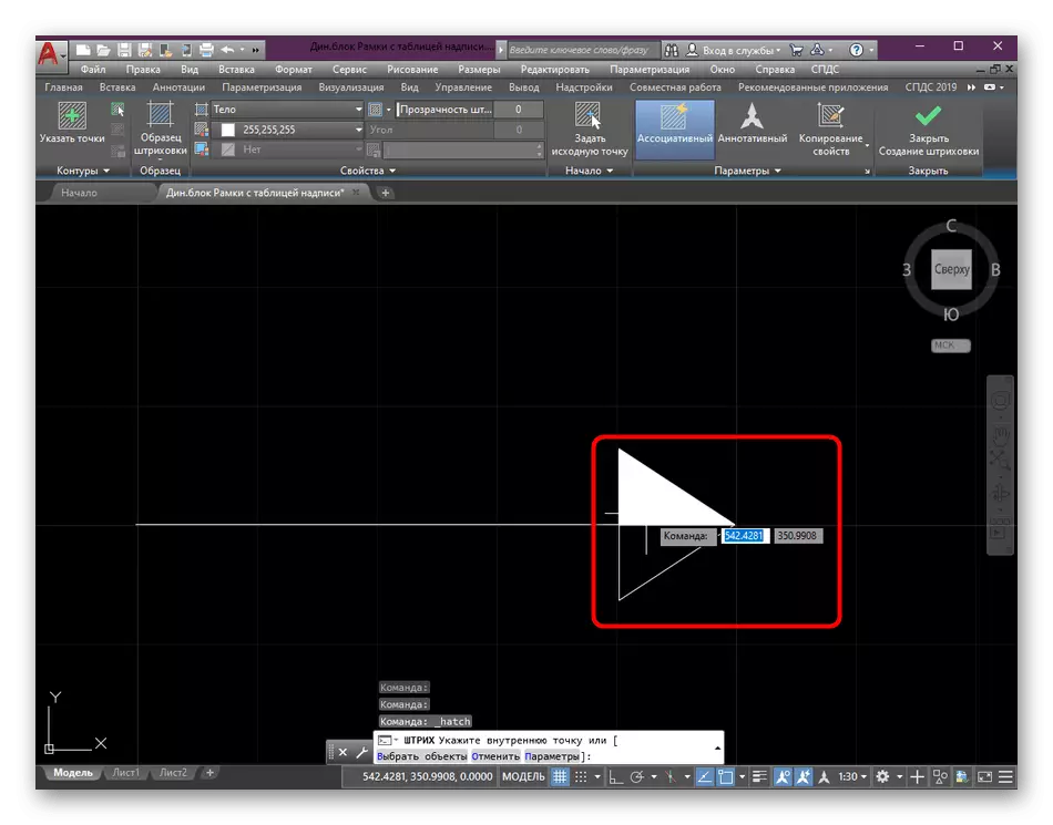
- Slide each side of the arrow.
- Upon completion, click on ENTER.
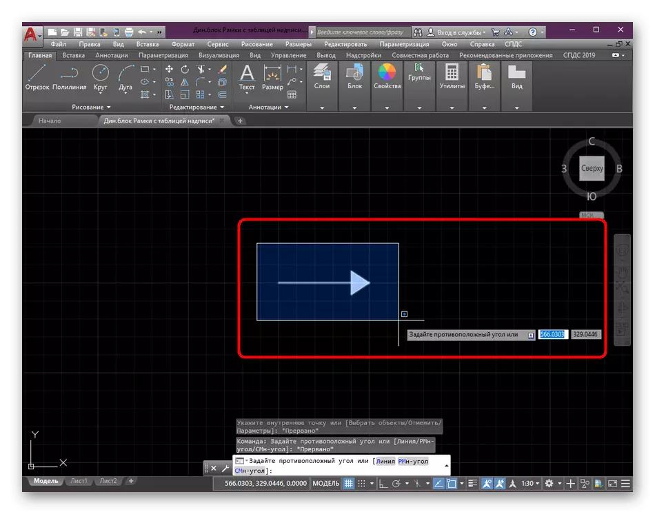
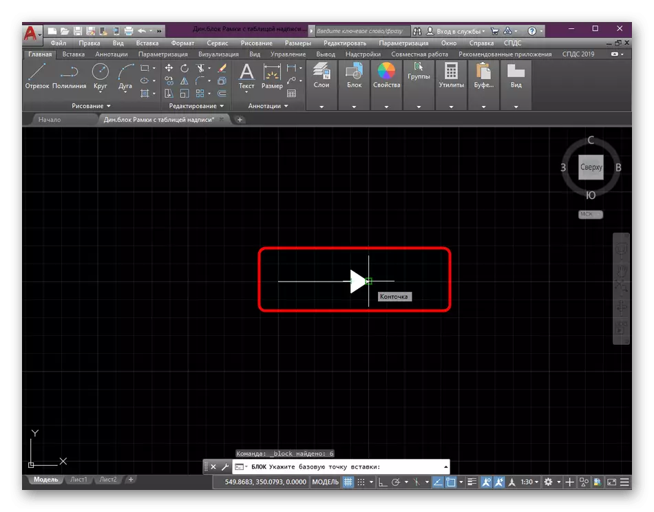
- The last step of work on the arrow will create a separate unit for it, since it is still inconvenient to manage all lines. First prior to normal selection, mark all the points of the arrow.
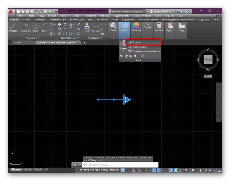
- Then in the "Block" section, click the "Create" button.
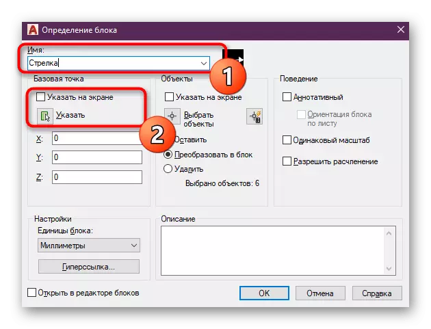
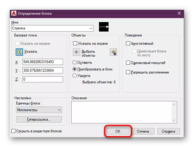
- A definition editor will open, where you enter the name for the block and go to the option of the base point. It will serve as a reference when moving or transformation of the arrow.
- On the drawing, you simply select any mouse-friendly point for you.
- At the end of the configuration, click on "OK" to apply all changes.
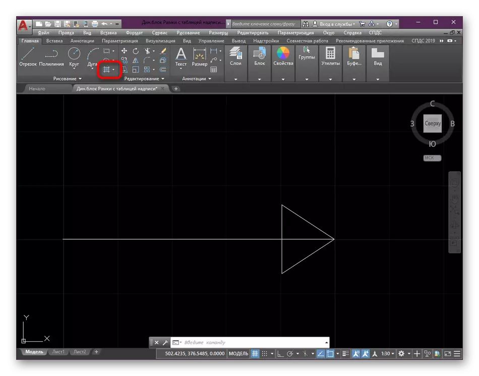
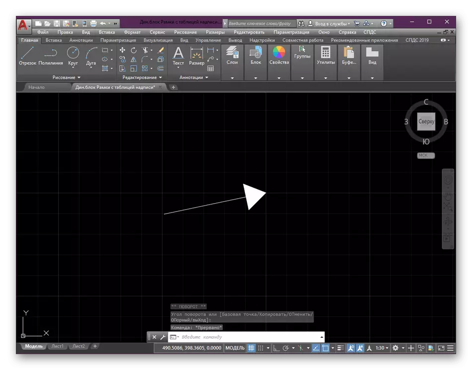
- As you can see, it turned out the most common arrow. Now it acts as a block, can freely move, edit and copy an unlimited number of times.
- In the screenshot below you see an example of the fact that there are no restrictions on creating an arrow by the considered method. It all depends only on your preferences and fantasies.
As for the hatching and grouping of the lines in the block: only one example of the execution of these actions was demonstrated above. In fact, the block functions are much more, and the hatching can be made by different options. Therefore, if you wish to study this topic in detail, we advise you to get acquainted with the following materials.
Read more:
Creating blocks in the AUTOCAD program
Creating hatching in AutoCAD
Method 2: Editing Sizes
Experienced users and some beginners know that the arrows in AutoCAD still exist, but they are only components of the size blocks. At the same time, nothing prevents how to create an arbitrary block, break it on all the components and leave the arrow itself. This is done as follows:
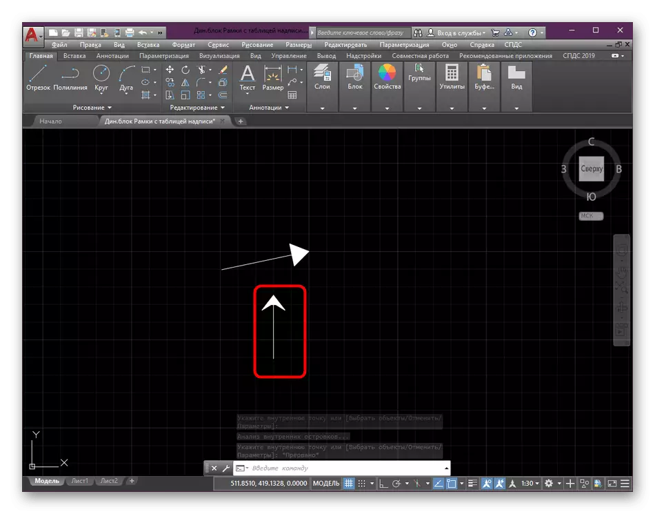
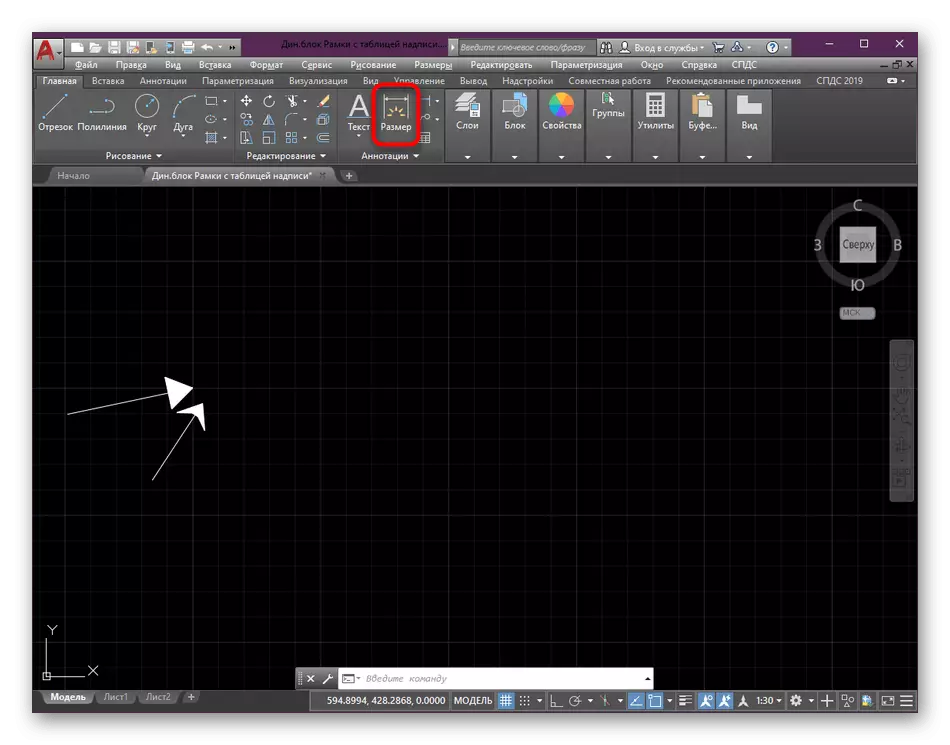
- On the main tape in the "Annotations" section, select the "Size" tool.
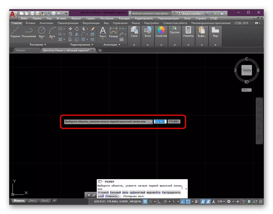
- Specify the first point to create a new size.
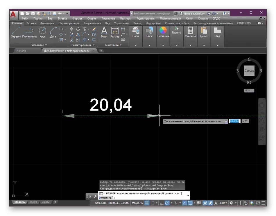
- Follow the prompts displayed on the screen to complete the creation of the segment. While the main thing is to optimize the length and size of the arrow, since the rest will still be deleted.
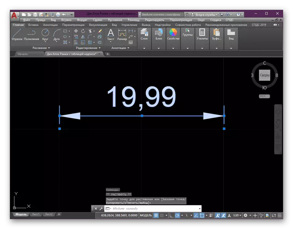
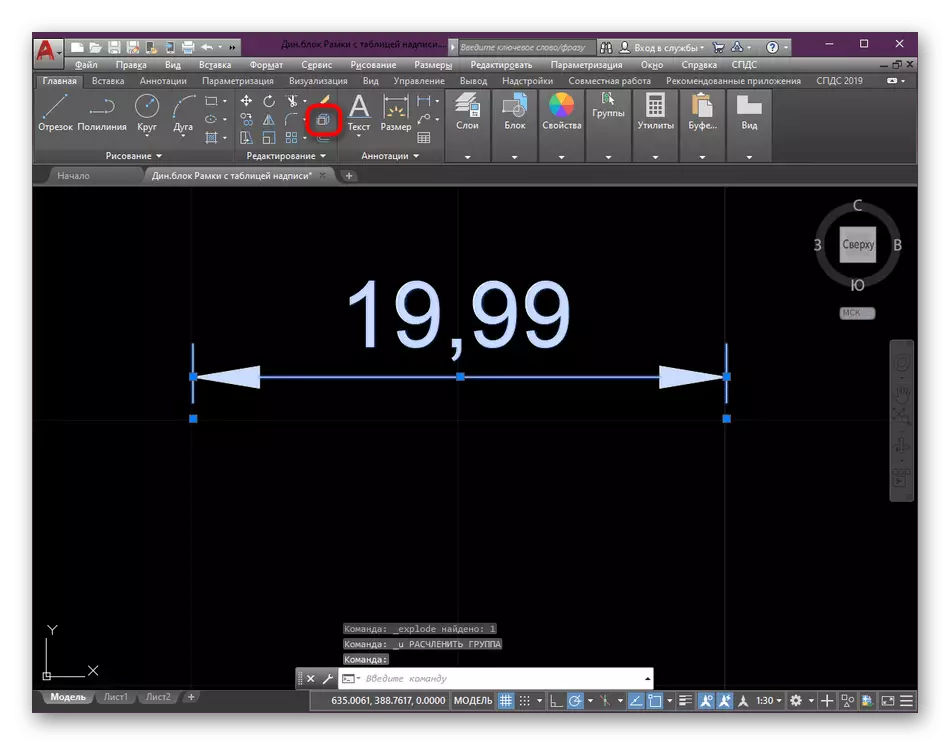
- Now you see that the size is a solid block, which means that it should be disdable or "blowing up".
- To do this, use the appropriate tool in the Editing section.
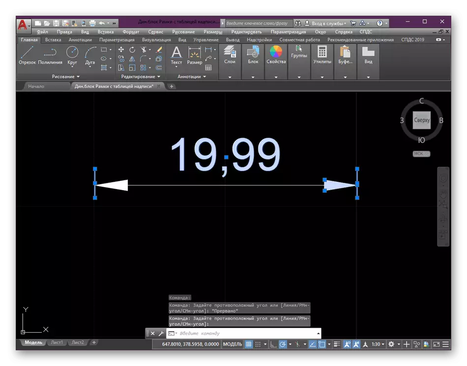
- Immediately after pressing the effect of the instrument will come into effect. After that, you need to highlight the number, individual segments and the excess arrow base.
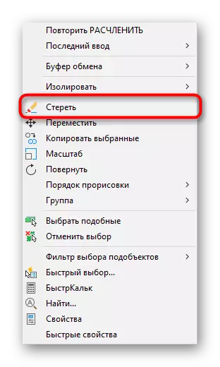
- Click the right mouse button and in the context menu that appears click on "erase".
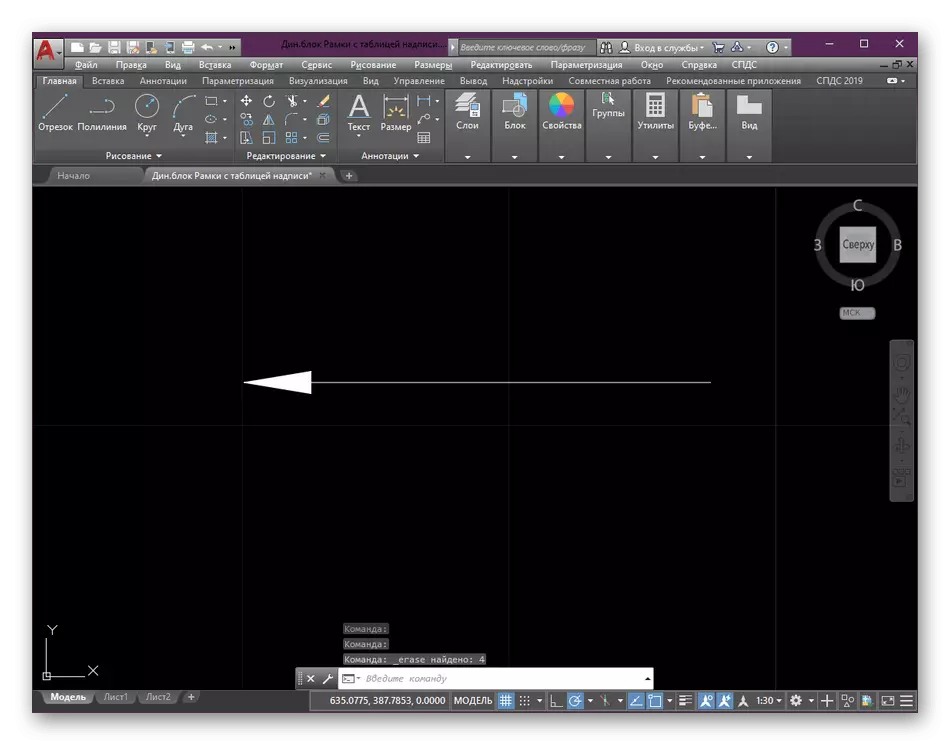
- As you observe in the screenshot, only one arrow consisting of two parts remained from the previously size. Combine them in a new unit as it has already been shown in the first method.
In this guide, the main functions were "size" and "dismember". Some newbies have not yet managed to master them, so we offer to do it right now, having studied the following materials in which the basic rules of interaction with these instruments are maximally described.
Read more:
How to smash the block in AutoCAD
How to put sizes in autocad
Method 3: Use of Polylines
Polylnia acts as a complex primitive, which consists of interconnected segments. Draw an arrow in this way will be easiest, however, it should be borne in mind that in the future, due to the characteristics of the Polyline structure, it will be facilitably edited.
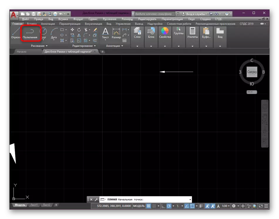
- In the "Drawing" section of the main ribbon, select the "Polyline" tool.
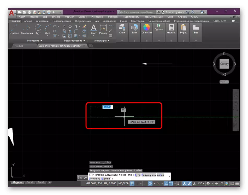
- You should not specify any segments, just Mouse over any area of drawing.
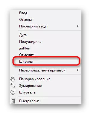
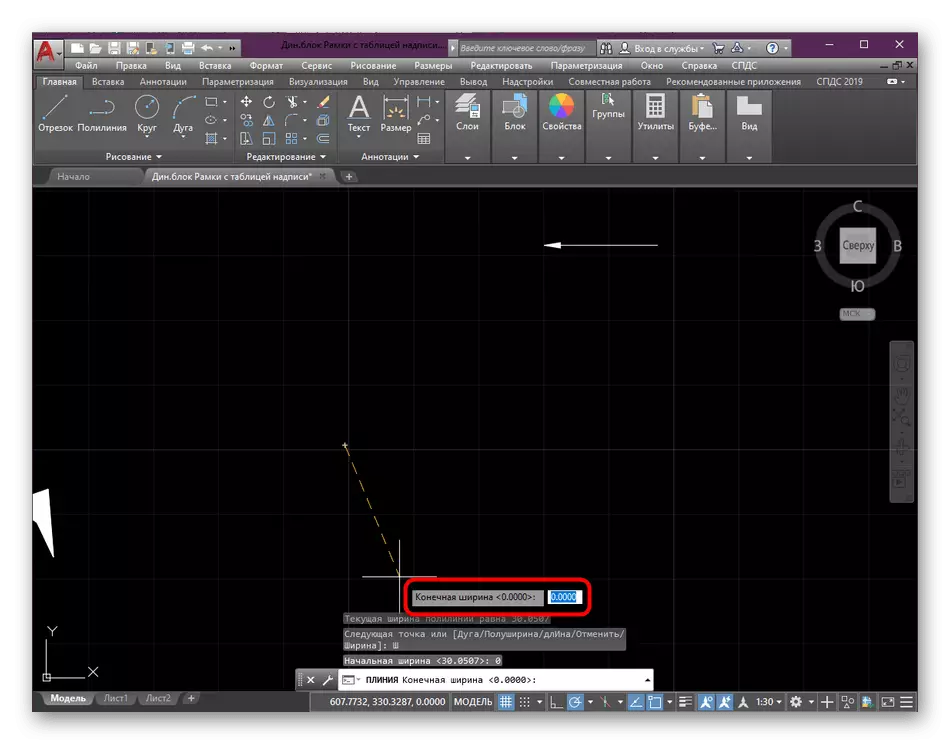
- Then click the right mouse button and go to edit the "Width" parameter.
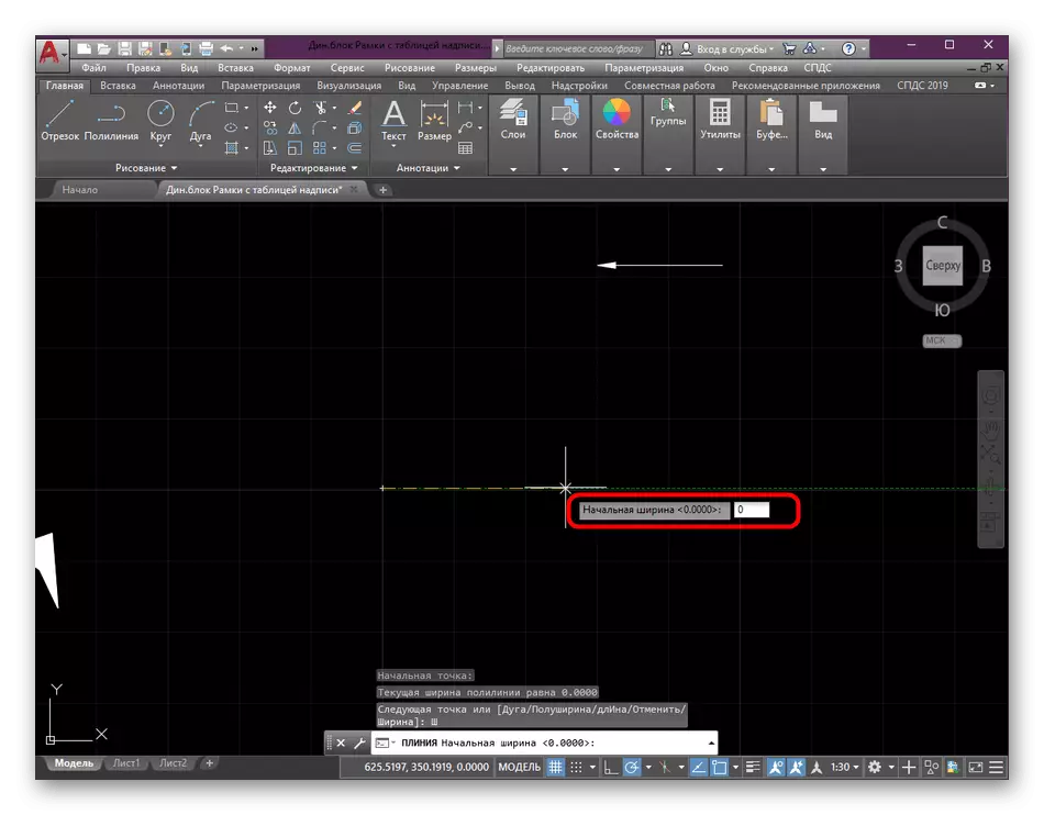
- Set the starting width by scoring the number "0" from the keyboard, as it will be the end point of the triangle.
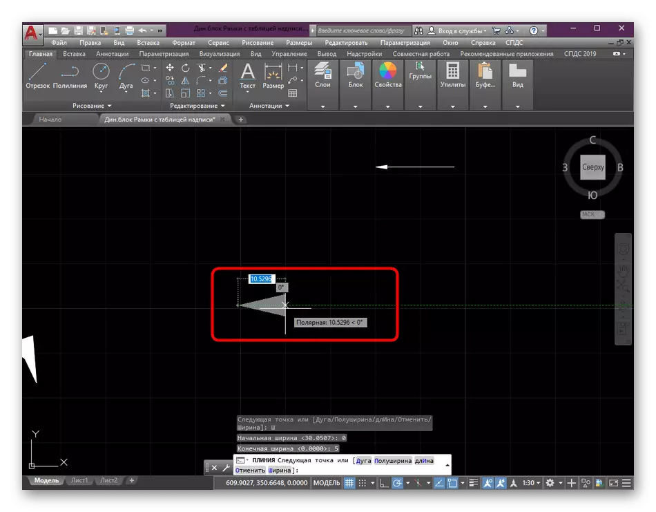
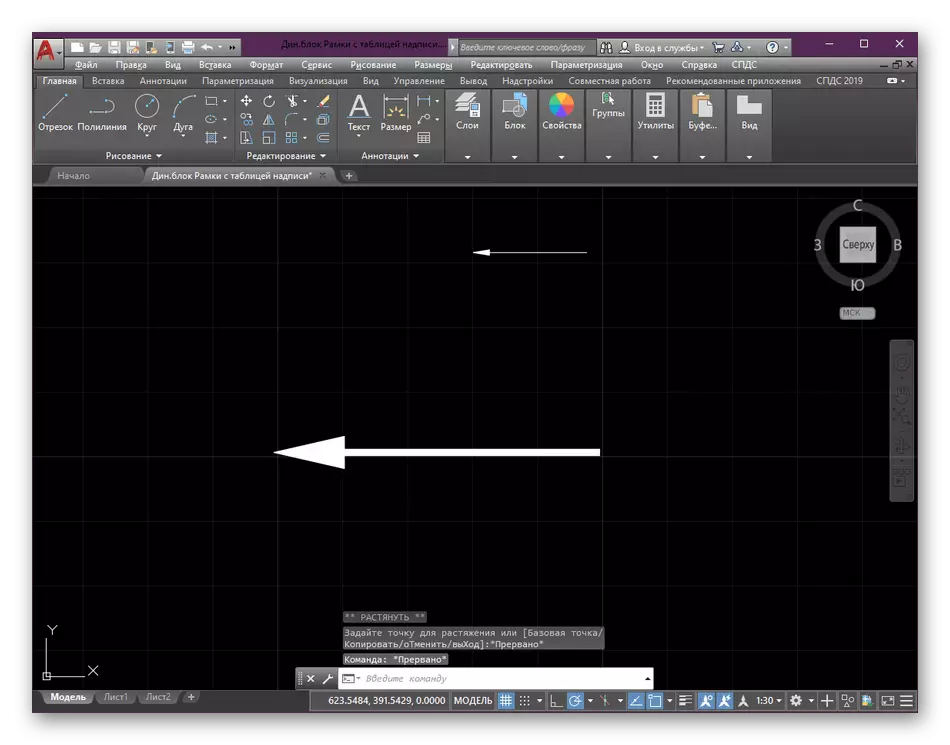
- As the ultimate width, enter any suitable reasonable value.
- After immediately there are changes made. At any time they are available for editing, if suddenly something was indicated not so.
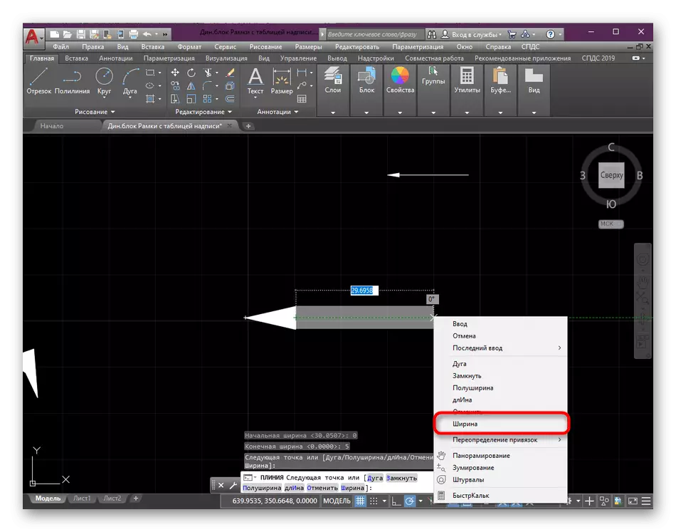
- Tap PCM again and select "Width".
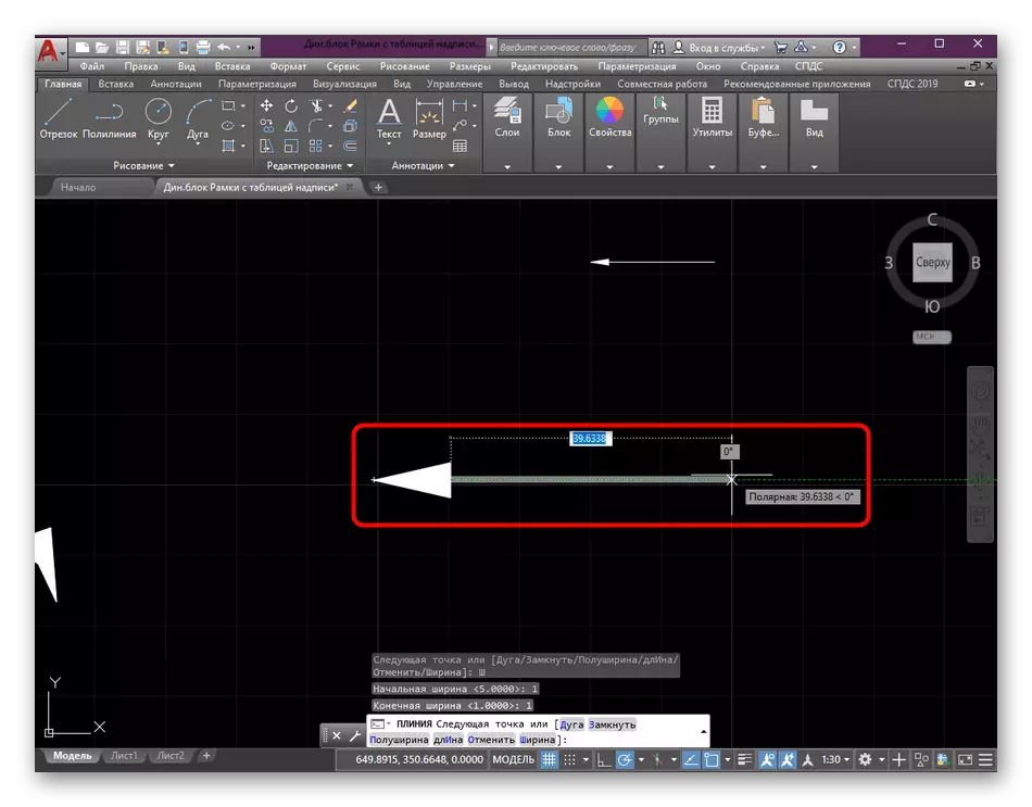
- Put the initial and endpoint into the same values by creating a thickness of the line that comes from the base of the arrow.
- On this, the creation of a polyline in the necessary form we needed successfully completed.
At the end of the previous methods, we gave references to detailed lessons on the use of the instruments mentioned, do it now. We just touched on a multiline, but this instruction does not reveal all its potential, so in other materials on our site you can thoroughly examine all aspects of this function.
Read more:
How to convert to Polyline to AutoCAD
How to combine lines in AutoCAD
We offer to learn about additional opportunities in a separate learning lesson, calculated mainly on poorly serious users, where the author collected all the most popular and frequently used from the AutoCAD program.
Read more: Using AutoCAD Program
Above you learned about the three available options for creating an arrow in the autocada. As you can see, it is possible to do this simply, but it will still take a certain amount of time, therefore we recommend to pre-prepare several templates and copy them if necessary.