

If the drawing in AutoCAD is created for working purposes, the presence on the frame sheet almost in all cases is necessary. It not only sets the edges of the drawing, there are also separate blocks with the main and auxiliary information about the project. Usually, users when performing a task receive a ready-made framework or you need to download existing designs created by GOST. Today we want to show how to add and configure such a frame after downloading.
Add and configure the frame in AutoCAD
Note that this material will be devoted to configuring the downloaded frame. If you want to create it yourself, you will only need to organize an appropriate dynamic block consisting of primitive rectangles. This operation does not need additional explanations, and all the necessary information you will find in our other materials by turning on the links below.Read more:
How to create a block in autocad
Dynamic blocks in AutoCAD
Creating a pairing in AutoCAD
Creating chamfer in AutoCAD
Step 1: Moving the downloaded frame in the drawing
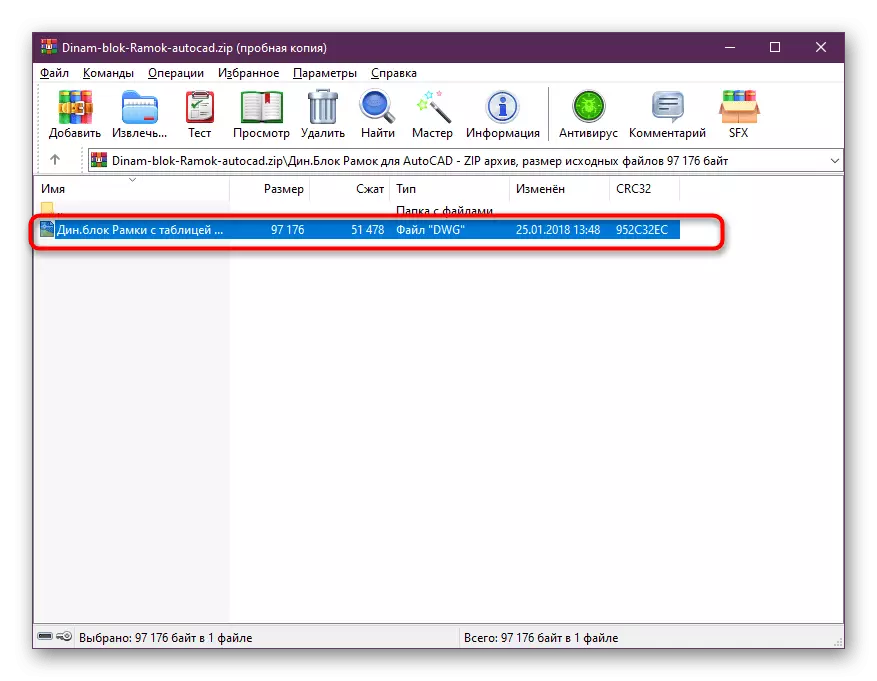
The first stage is to move the frame to the drawing, which is literally a couple of clicks. To begin, move the file with the frame to the local storage or download it from the source found.
- Usually files are stored in separate archives, so drag them at any convenient place on your computer.
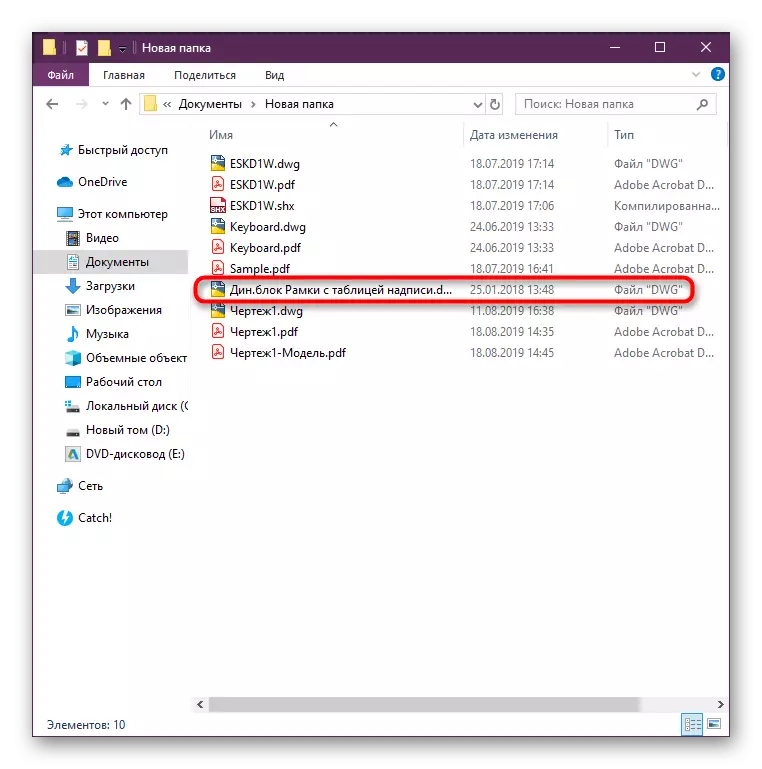
- Go to the place where the file was saved, and drag it to AutoCAD.
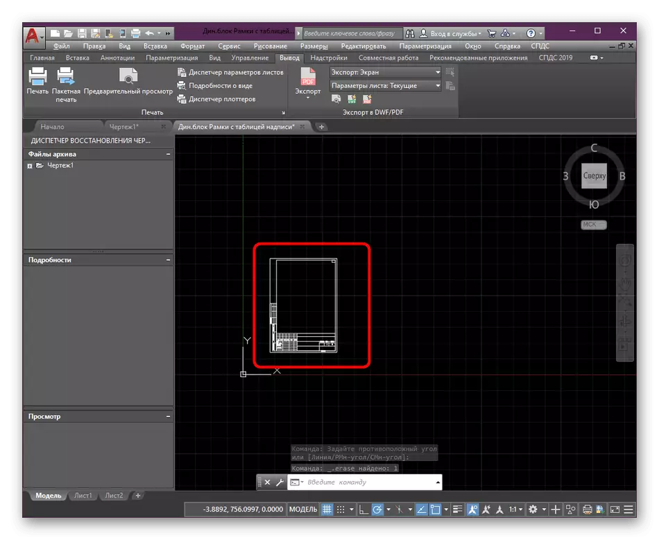
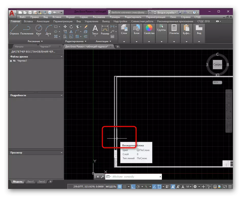
- Add it to the drawing by selecting the best location.
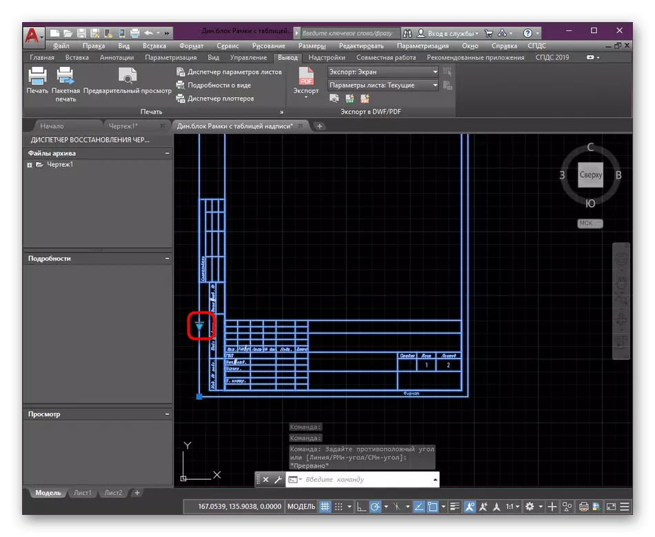
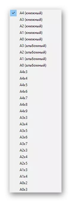
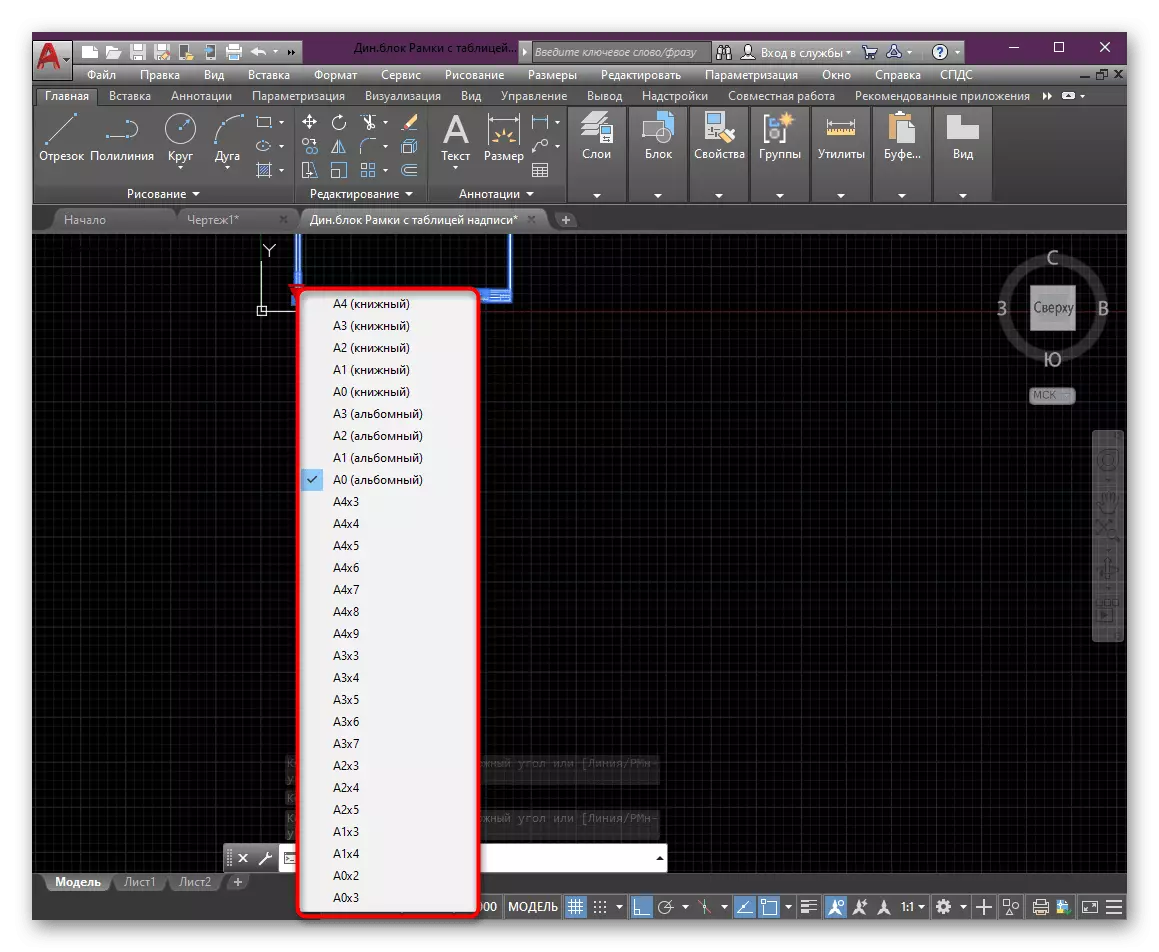
- Use a blue triangle on the frame block in order to quickly change its size.
- Of course, this setting is not present everywhere, but in most cases it is available, and you can choose absolutely any standard format.
In the same way, any framework is placed if its format is supported by autocadal. Such files are usually distributed in DWG, so no problems should occur with the opening.
Step 2: Configuring the Content Frame
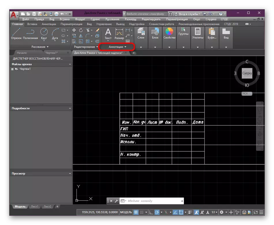
By default, each frame consists of a certain number of parameters and inscriptions performed in any style. It all depends on what kind of file you will be given or you download yourself. However, after opening it in AutoCAD, the frame can be in every way to edit. To begin with, standardize the font under your project:
- In the "Home" tab, find the "Annotations" section and deploy it.
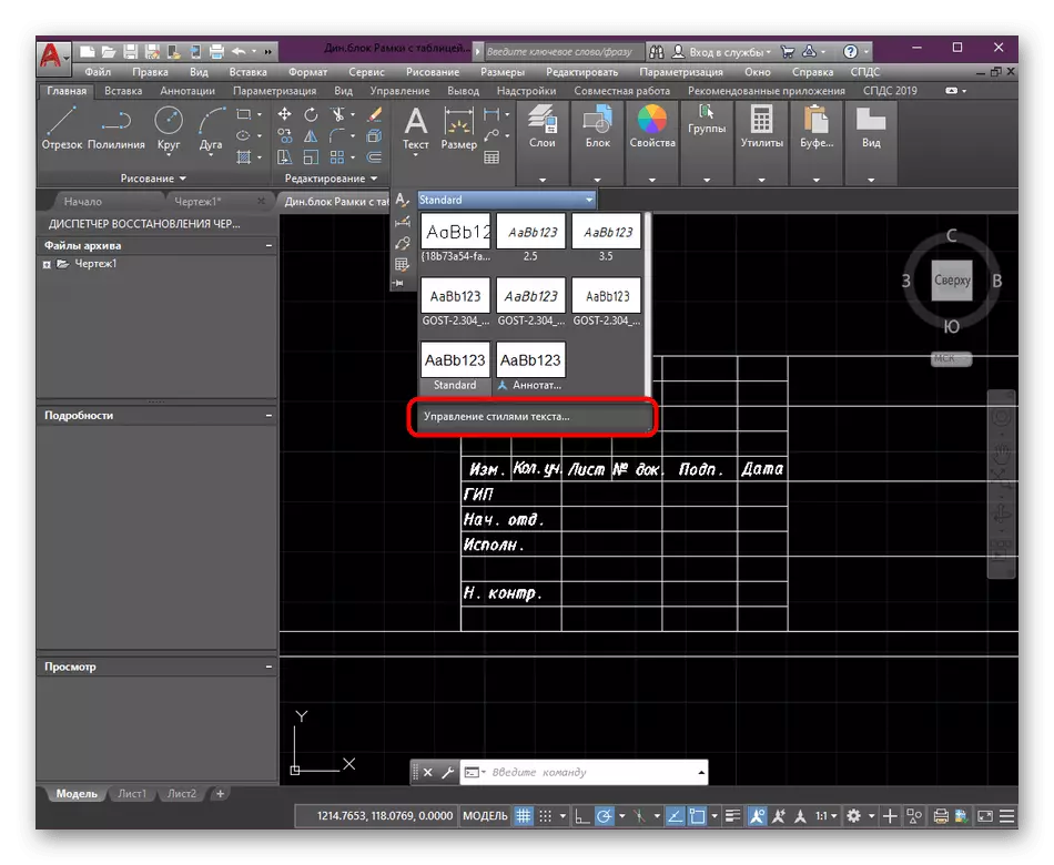
- In the font style you will see an extension button "Text Styles".
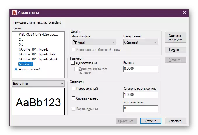
- Now there will now appear in which you can edit each existing style on the project as you consider it necessary.
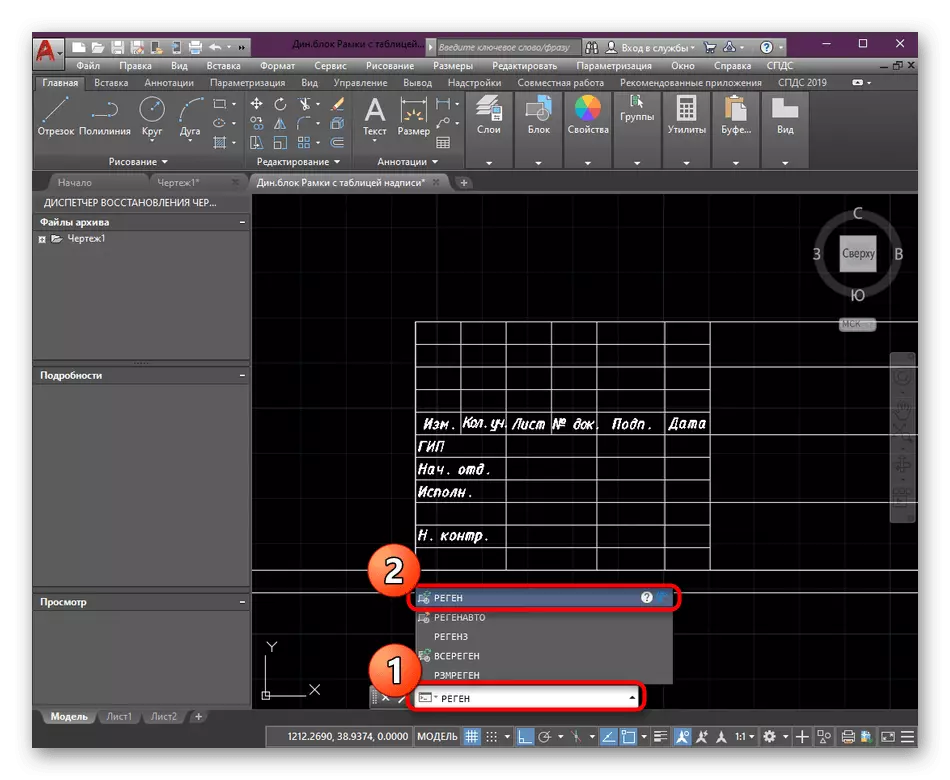
- After applying all changes, it is necessary to regenerate the drawing so that everything will be displayed correctly. To do this, in the command prompt, type the word regen and click on ENTER.
Editing, deleting or adding present parameters is made a little more difficult, because for this you will have to go to the "block editor" and call a special panel. However, after familiarizing with a small instruction, the product of this operation will become more understandable.
- Highlight the frame by clicking on it once the LKM.
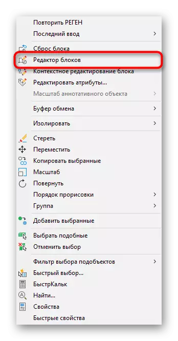
- Next, click the right mouse button and in the context menu that opens, select "Block Editor".
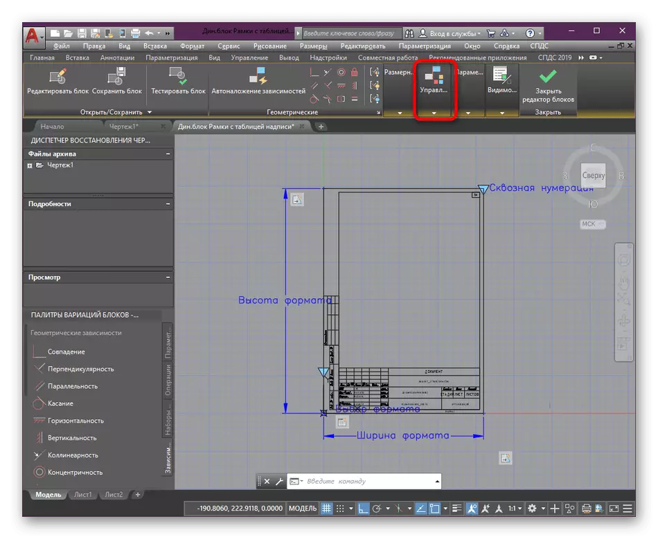
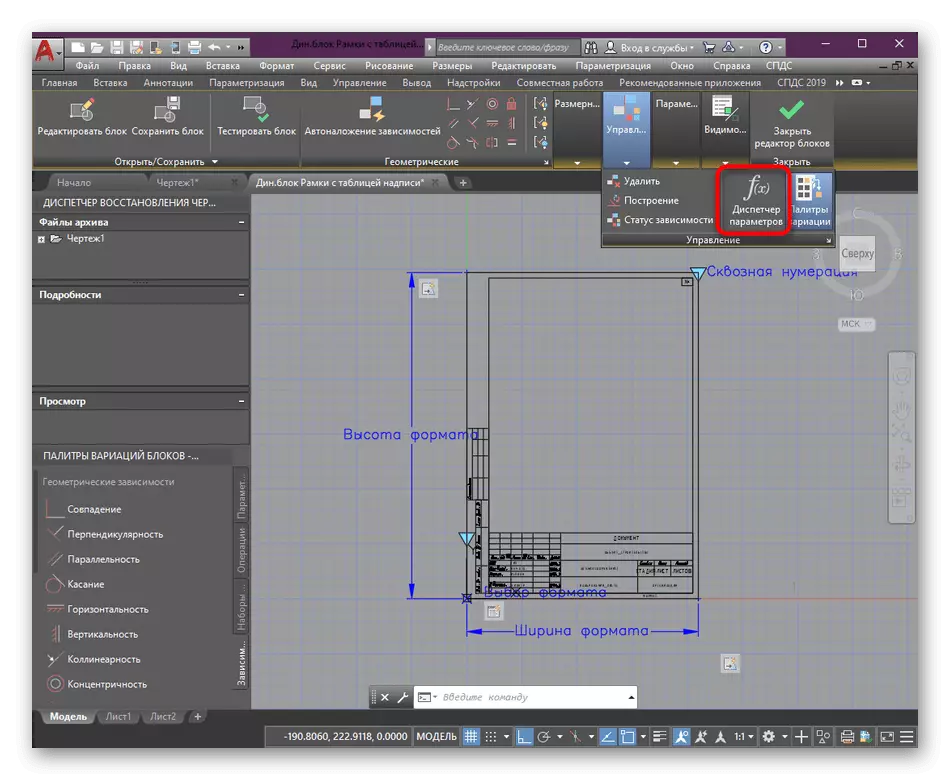
- Wait for the module to start, where in the tape, expand the control tools.
- Select the "Parameter Manager" item to display this panel.
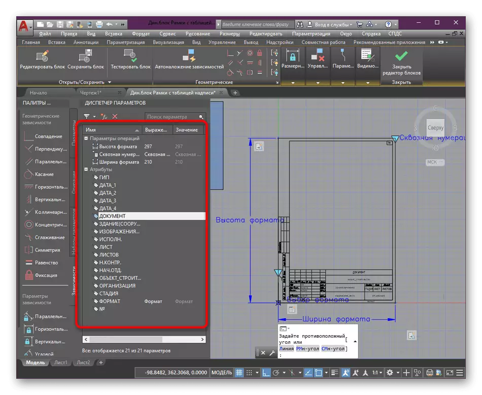
- It will appear on it all attributes and parameters that can be renamed, add values, specify the associated parameters or removed at all.
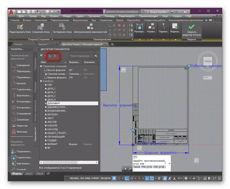
- Deleting and adding attributes occurs by clicking on specially designated buttons at the top of the panel.
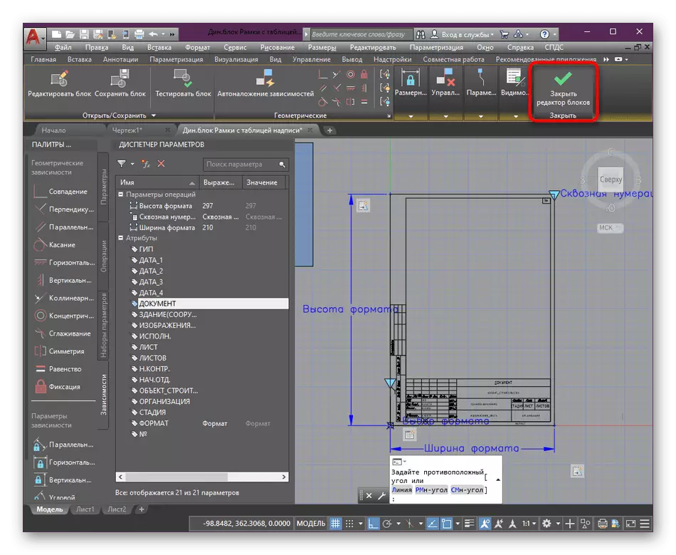
- Upon completion of the block changes, close the editor, be sure to confirming the storage of changes.
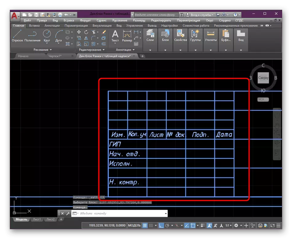
Step 3: Adding Attribute Values
For each frame, the user defines certain values to attributes that characterize the project. This includes employee names, dates, sheets, any values and other information. Edit such values on the already existing dynamic block is very simple:
- Double-click on the left mouse button to open the editor.
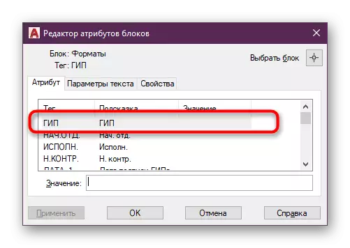
- In the Lay the desired attribute window, select it and enter the necessary characters in the "Value" field.
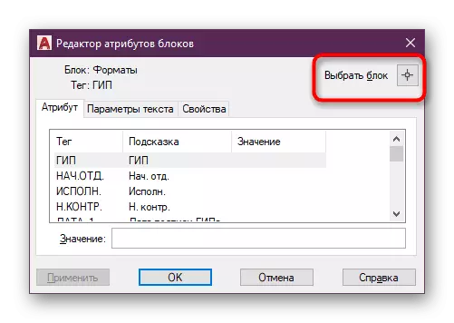
- If you need to choose another edit frame, just click the "Select Block" button.
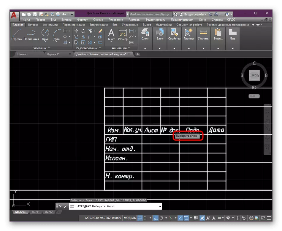
- In the workspace, specify the item you want to edit further.
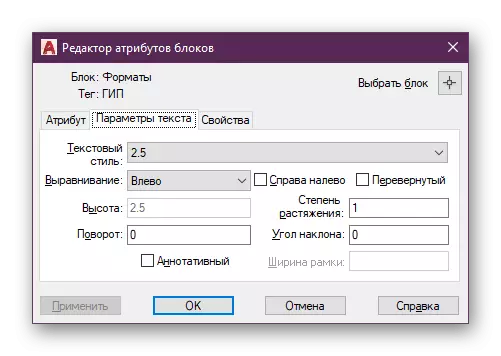
- I also want to note that in the "Block Attribute Editor" window, there is a separate tab called "Text Parameters". In it, you can change the font style about the same principle as shown earlier, but with some limitations.
This is so simple, the standard framework is customized for user requests. After making all the values, they will be displayed in the corresponding fields in the drawing and will help those people who will work with it, to get all the necessary information.
Step 4: Copy Frame on Sheet
As you know, the design and further printing of the drawing occurs in the "Sheet" module. Here the user sets up the paper format, adds some elements and applies additional parameters. Now we will not dwell on it, and let's talk about the transfer of the frame to further display it when printing.
- To begin with, specify the appropriate format by editing the dynamic unit.
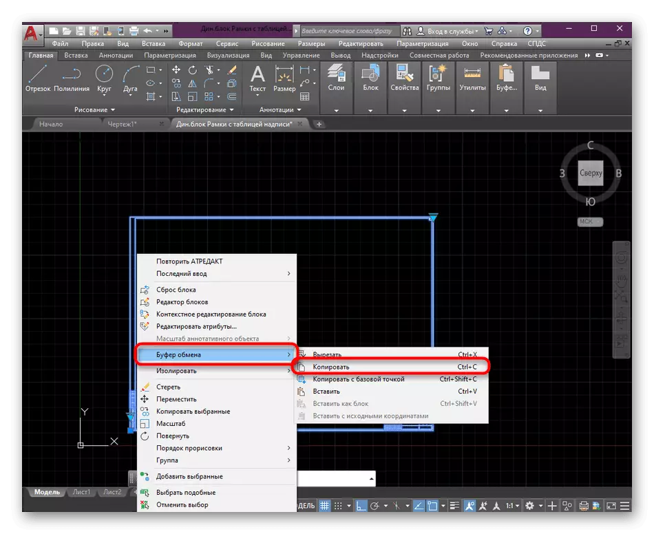
- Click on the PCM frame and in the context menu Mouse over the clipboard by selecting "Copy". The same action can be made by holding the Ctrl + C key combination.
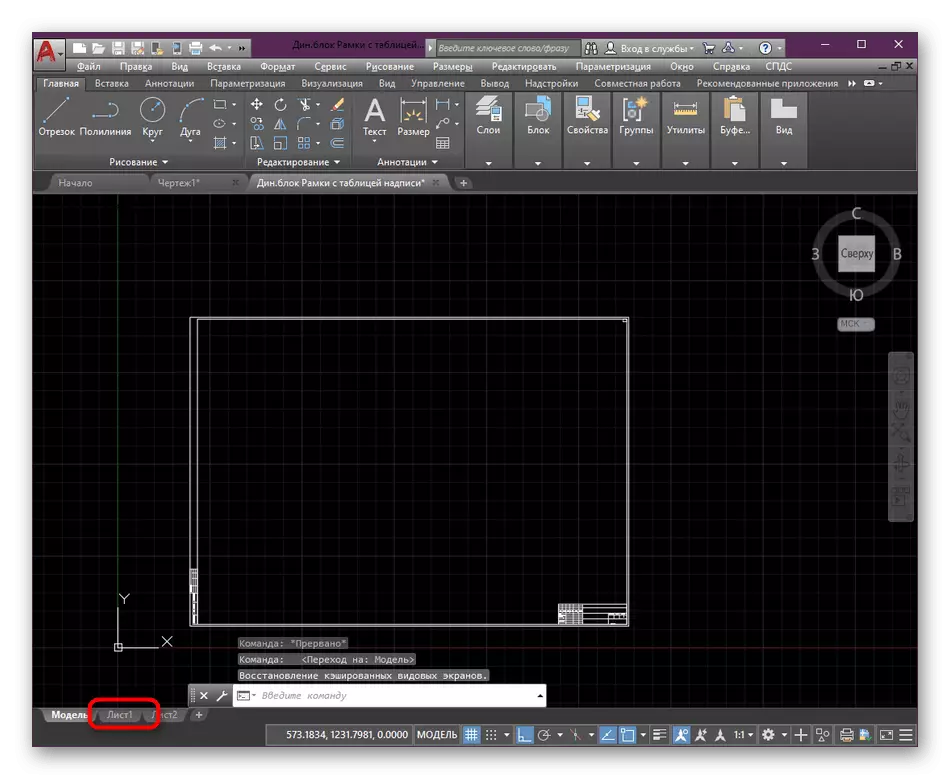
- Then go to the Sheet tab where you want to place the frame.
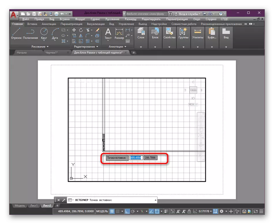
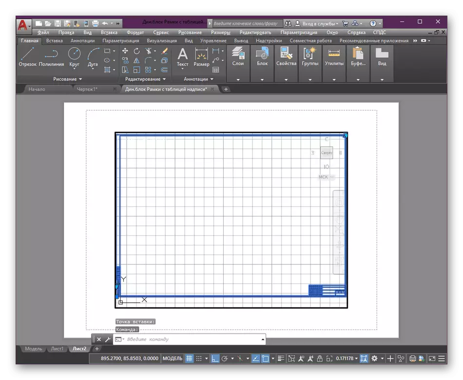
- Here, press Ctrl + V to insert a frame-copied frame. Select a convenient location by specifying the insertion point.
- Now you can proceed to a more detailed location of the elements or immediately send a finished drawing to print.
We still want to note that novice users will be useful to familiarize themselves with the additional training material on the topic of interaction with the basic tools and the functions of the software under consideration. Thanks to this, you will deal with the main aspects of the drawing setting and auto channel parameters.
Read more: Using AutoCAD Program
Now you know about the principle of adding and setting the frame in AutoCAD. As you can see, this is quite simple, the main thing is to find the frame itself. As for the creation of its own dynamic block, performing the same function, this article will also be useful to those who are first faced with the implementation of such a task.