

Dynamic blocks in AutoCAD at first glance look like the most common standard group of primitives. However, there are certain parameters characterizing these types of objects. They are focused on the size and location and easy to edit the size and easily. The main stop here is made on moving without any changes to other elements of the drawing, as well as an increase in size, width or other values on the discrete settings that the user itself specifies during the creation of the unit. Today we want to talk in detail about dynamic blocks, step bypassing their application.
We use dynamic blocks in AutoCAD
The format of this material will be constructed around the analysis of one simple example of using a dynamic block with phased actions. This will help even beginner users to master the interaction with these groups and sort out their applications. Let's start from the first step - the creation of an ordinary block.Step 1: Creating a Block
Initially, the dynamic block is standard static, and only later options and operations are applied via the editor to it. We will talk about this later, and now we will analyze the most banal process of creating a group, if you, of course, have not yet done this earlier.
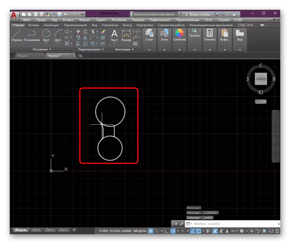
- Find all the items in the drawing you want to merge into the block. Highlight them by climbing the LKM and conducting an allocation area.
- After that, all primitives should shine with color. In the "Block" section, click on the "Create" button.
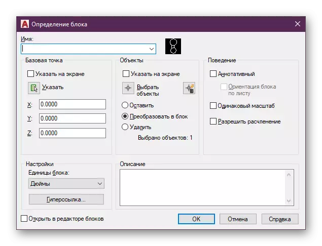
- Auxiliary menu will open under the "block definition". In it, set the name, additional parameters and go to the base point selection.


It was a simple and fast instruction on the demonstration of creating a standard group from primitives. If you first encounter a solution to a similar task, we advise you to get acquainted with a separate article on this topic on our website, in which each stage of creating a block and control of it is described in more detail.
Read more: Creating a block in AutoCAD
Step 2: Adding Dynamic Block Parameters
Now it's time to format the usual block into dynamic by specifying the parameters and operations for it, which is performed in a separate module called "Block Editor". Let's start from the most basic - setting parameters. They refer to what type of change will occur, for example, stretching along line, point, rotation, or alignment.
- Hover the mouse over the unit and click on it twice with the left button.
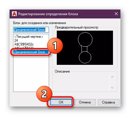
- In the selection menu that opens, specify the same group you want to do dynamic, then click on "OK".
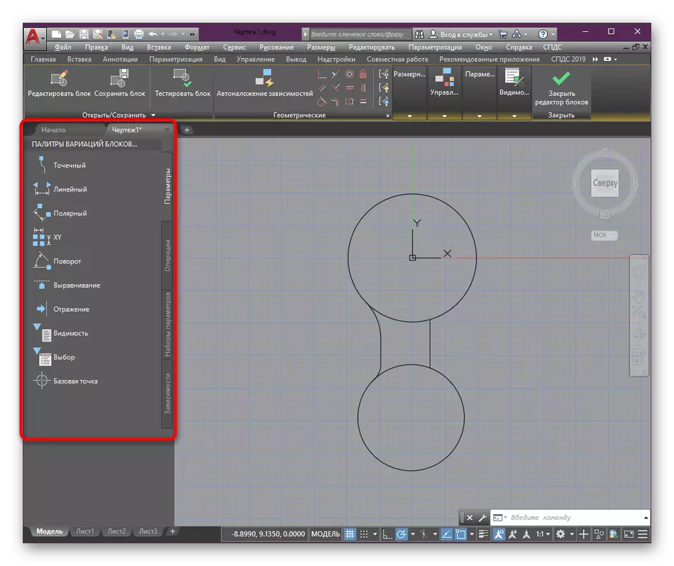
- At the moment, pay attention to the palette panel of block variations. It is in it that will be carried out further settings.
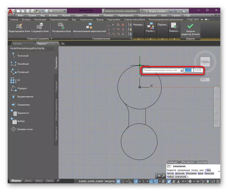
- We will analyze an example of changing the size of the object in linear mode. You can choose any of the available types of parameters, which is necessary for a particular block.
- Next, select the initial and end point of the object, which will indicate the scope of the parameter. In our case, this is an absolutely whole object. Therefore, as an initial point, we specify the upper line.
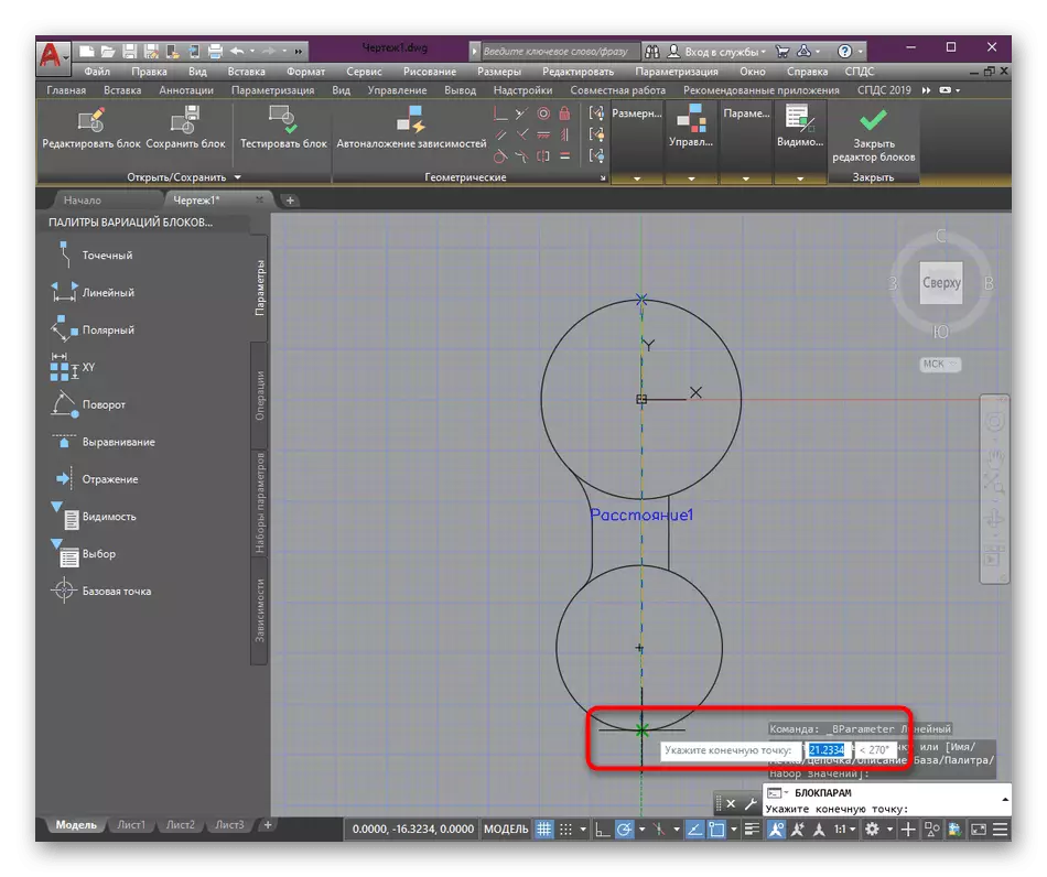
- As the ultimate - the bottom, by clicking on it with the left mouse button.
- A separate element called "Tag" will appear. Place it near the object so that it does not interfere with the interaction with the block.


As you can see, the application of the parameter does not take much time. Additionally, it should be noted that you can assign several variations at once, choosing which of them to use. It is important to edit the name of the labels in order not to get confused in all buttons.
Step 3: Assigning an operation
As already mentioned above, after creating parameters, the moment occurs when you want to specify an operation that will be carried out with the specified values. We chose the standard "Stretch" option, allowing you to change the block size using the specified discrete values (we will talk a little later about them).
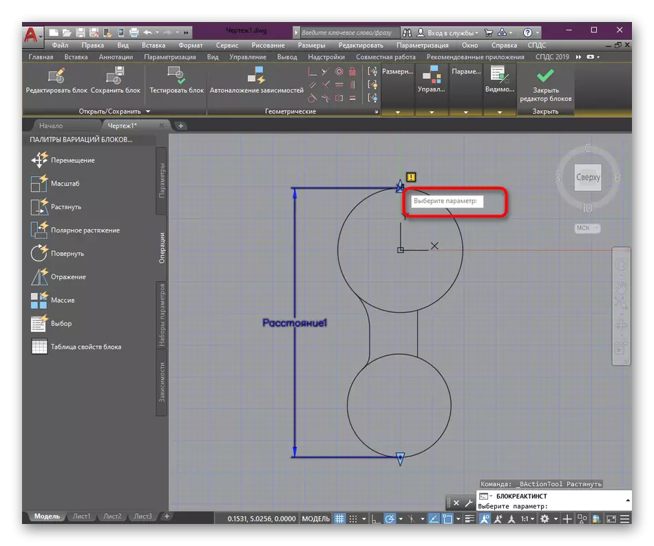
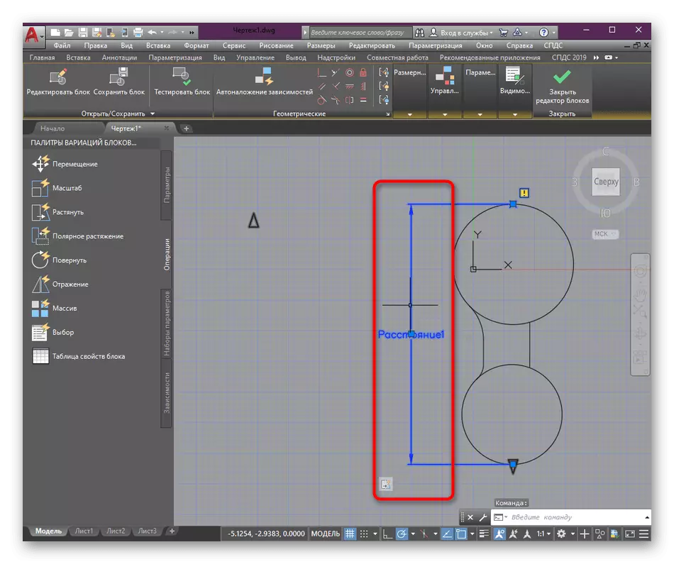
- Move into the section "Operations" and there click on one of the options present, for example, to "stretch".
- After that, you will need to specify the parameter for which the selected area will be applied. Just click the LX for the label that was selected earlier.
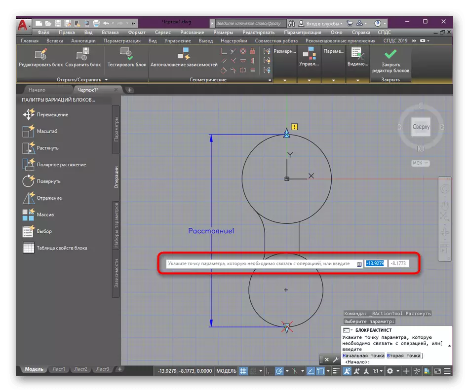
- Next, the notification will appear on the screen. Specify the point of the parameter you want to associate with the operation. " Now it is to get a point that will continue to have a type of a button in the form of a triangle. Pressing it allows you to apply the generated operation. Just specify any convenient location of this point.
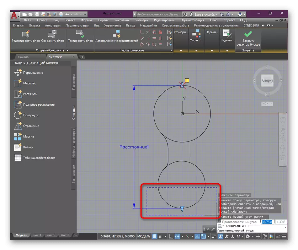
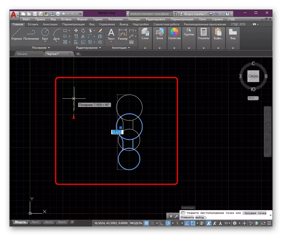
- Then a new tip appears with the text "Specify the first angle of the stretch frame." This denotes that now you need to create a frame where the elements stretched in full form will be included when valid values. The movable primitives will fall into the area not completely.
- You see the correct example of the selection in the screenshot below.
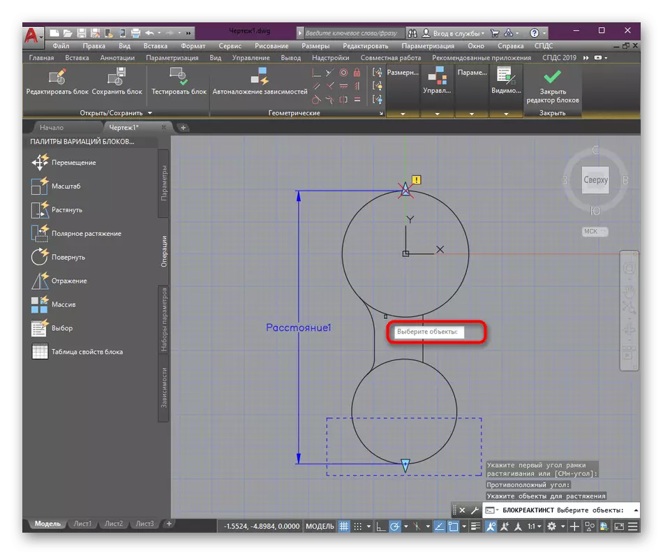
- The last step of the setup is the selection of an object included in the operation area. In our case, this is the entire block entirely.
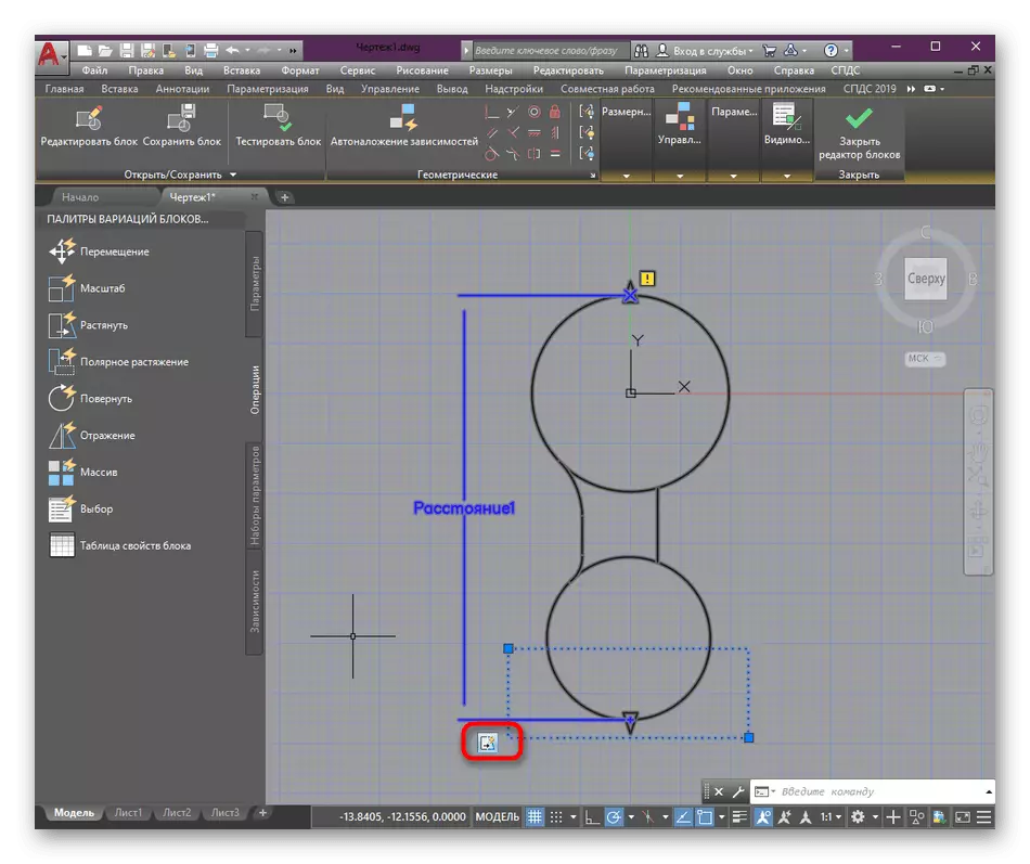
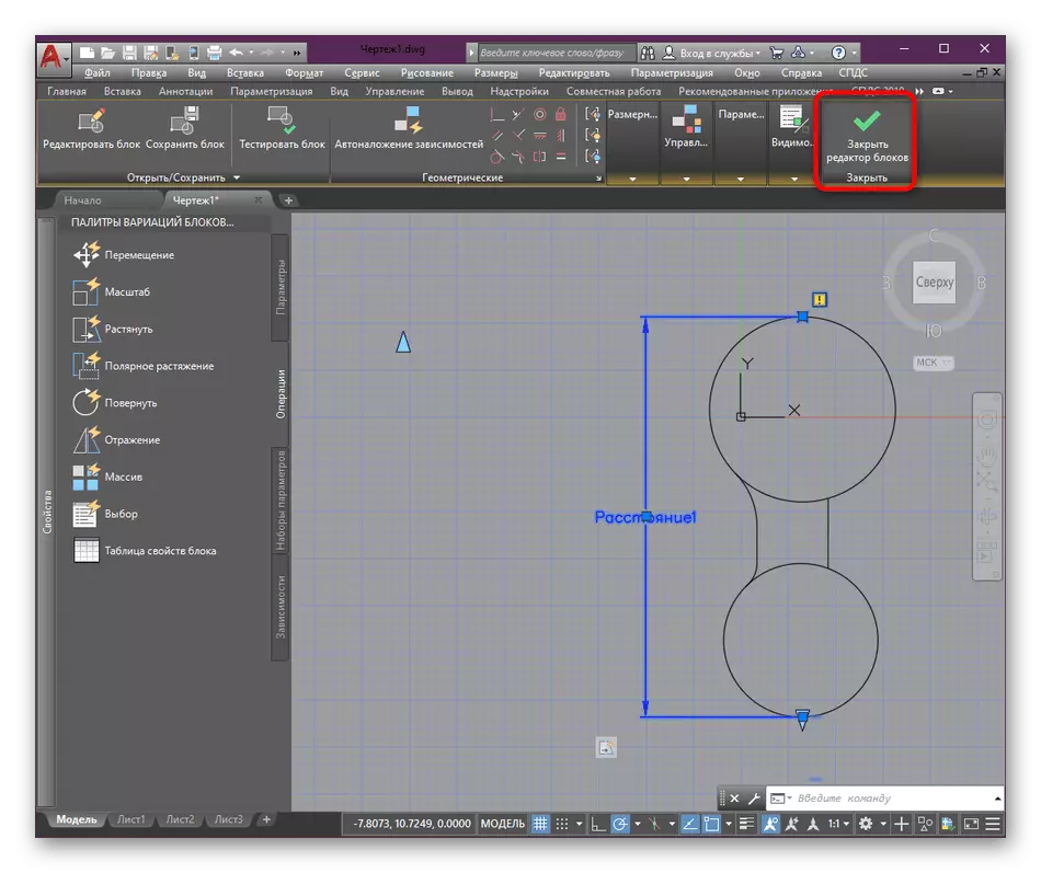
- At the end of editing, the corresponding icon appears on the left, indicating that the operation came into effect.
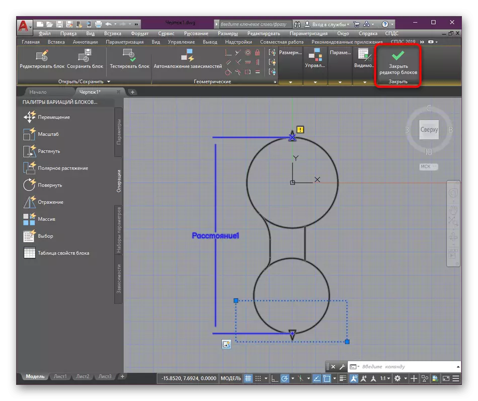
- Complete the work in the editor by clicking on "Close Block Editor".
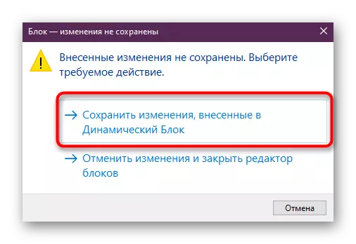
- Be sure to save all changes made.


Step 4: Installing Discrete Values for Block
The last stage of today's material is practically important, since it determines the dynamic of the block. Discrete values are manually installed by the user manually, which can be selected from the list to change the state of the object. Adding such values is as follows:
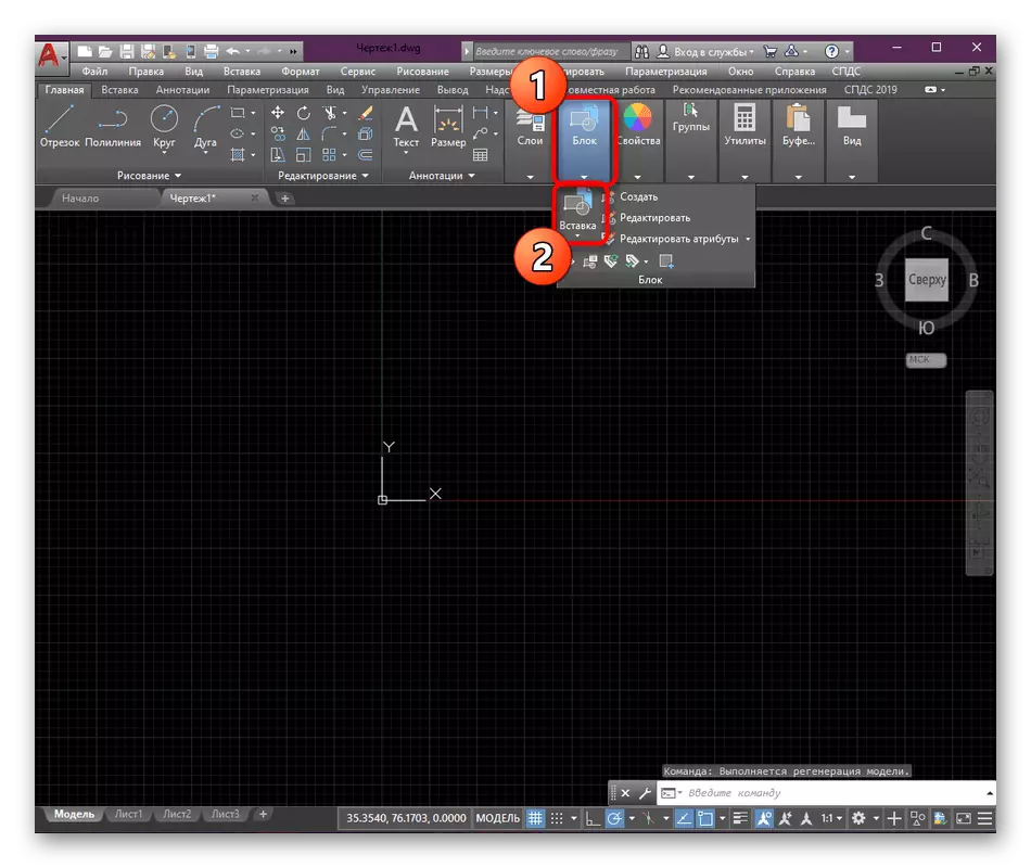
- To begin with, let's insert the created block to the drawing through the "Paste" tool.
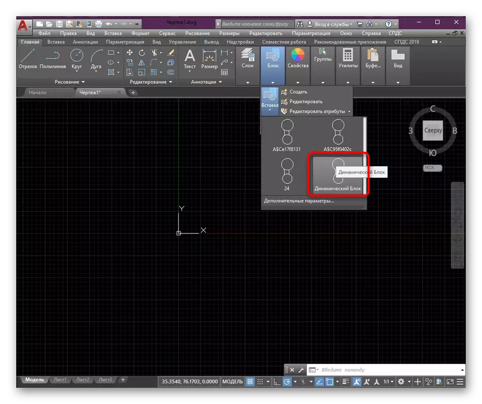
- In the menu that opens, simply select the desired string.
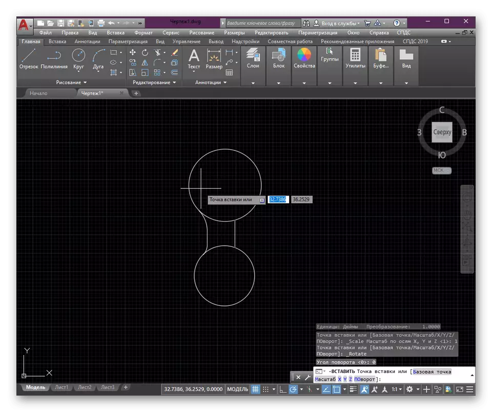
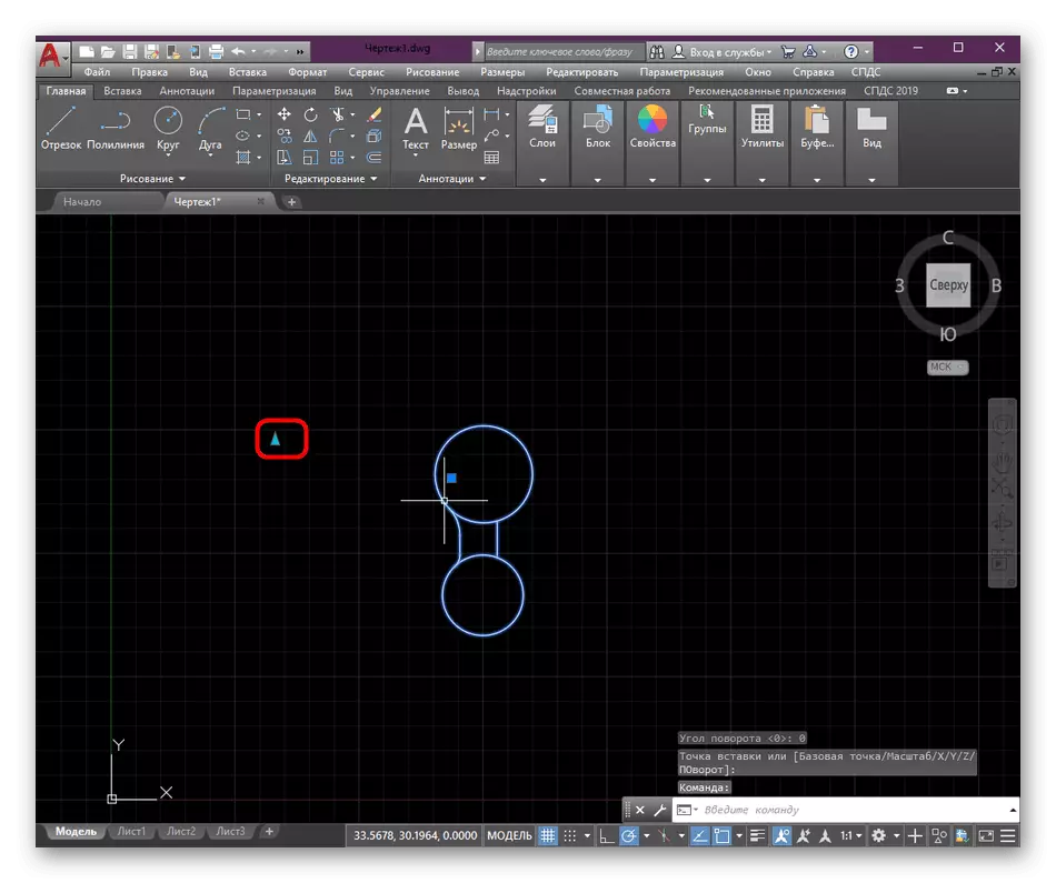
- After that, the group itself will appear in the workspace. Select the location point for it, and then click the LX.
- Pay attention to the triangle that was discussed earlier. He acts as a lever to apply block control options.
- Now pressing it allows you to stretch the group as you like, so you will correct it by setting discrete values.
- Highlight the group so that it caught fire in blue.
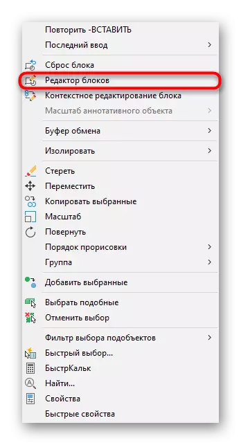
- Click on it PCM and go to "Block Editor".
- Here, select the parameter label.
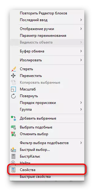
- Call the context menu by clicking on the PCM again, where to find the item "Properties".
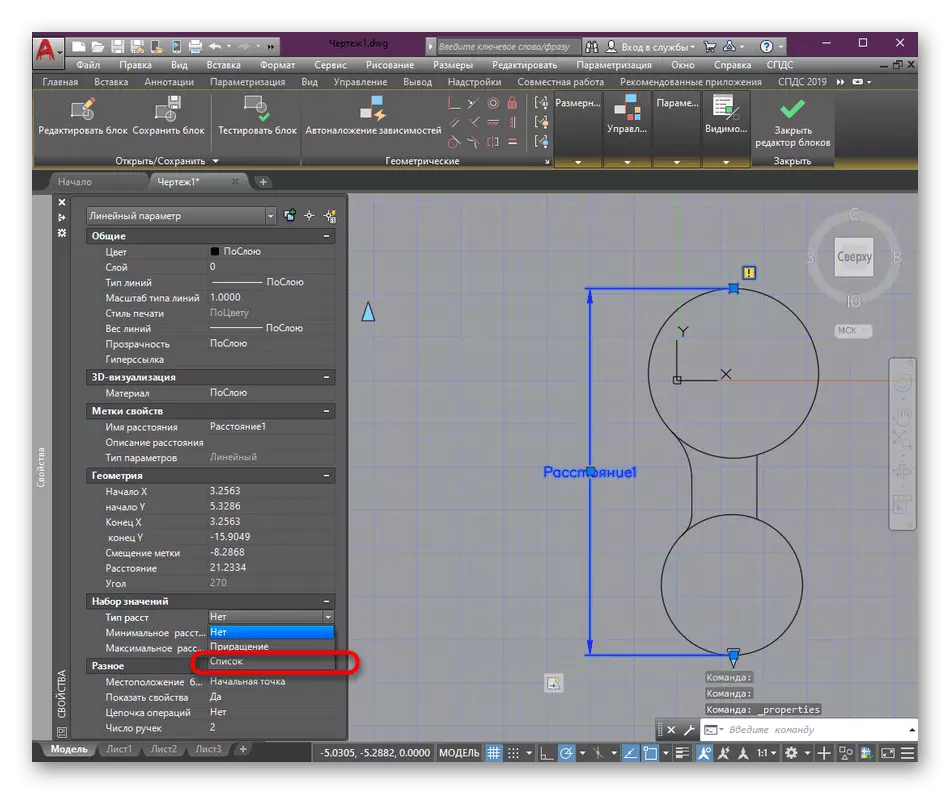
- The properties panel will be displayed on the left. In the "Set of Values" you need to find the item "Distance Type".
- Expand the menu to specify the "List" value.
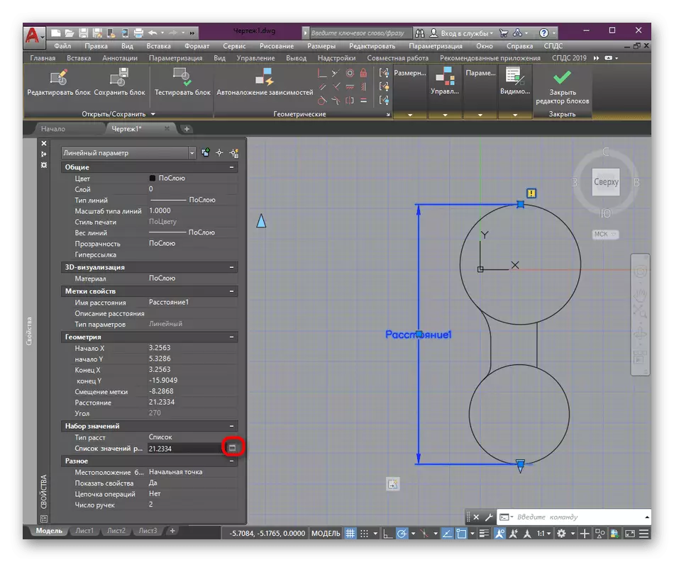
- Now the additional parameter is displayed below with the button in the form of a rectangle. On it and you should click.
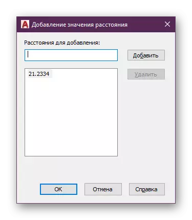
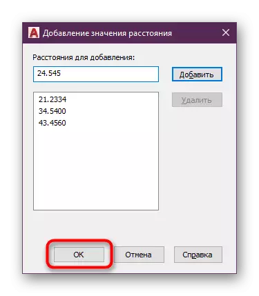
- In the "Adding Distance Value" menu, you can specify absolutely any fixed distances to which you plan to move the block.
- Add the option number to use suitable at any time.
- When you finish, click on the "OK" button.
- Close the editor.
- Confirm the saving changes.
- After that, when you click on the triangle, only discrete values can be specified as a distance.


As for the immediate editing of dynamic blocks in this software, it is carried out in a similar way, as in the case of conventional groups. Such objects can be renamed, deleted or split. More detailed instructions on all these topics can be found in our other materials, while moving below the links below.
Read more:
Rename blocks in AutoCAD
How to smash the block in AutoCAD
Removing block in AutoCAD
Now you are familiar with the concept of dynamic blocks in AutoCAD. As you can see, they are very useful and actively apply in a variety of drawings. However, bring the project to the perfect state of alone blocks is impossible. Here you need to apply additional tools and functions, the main of which are described in a special training article on the link below.
Read more: Using AutoCAD Program