

The scale in AutoCAD determines the size of the drawing area, which will fall into a frame with certain proportions. If you take a standard scale 1: 1, then this means that now 1 millimeter is displayed in its true length. However, sometimes users have the need to change the scale, which is associated with certain nuances of various projects. This can be done very simply in the "Sheet" section or when creating a print job.
Change the scale in the AutoCAD program
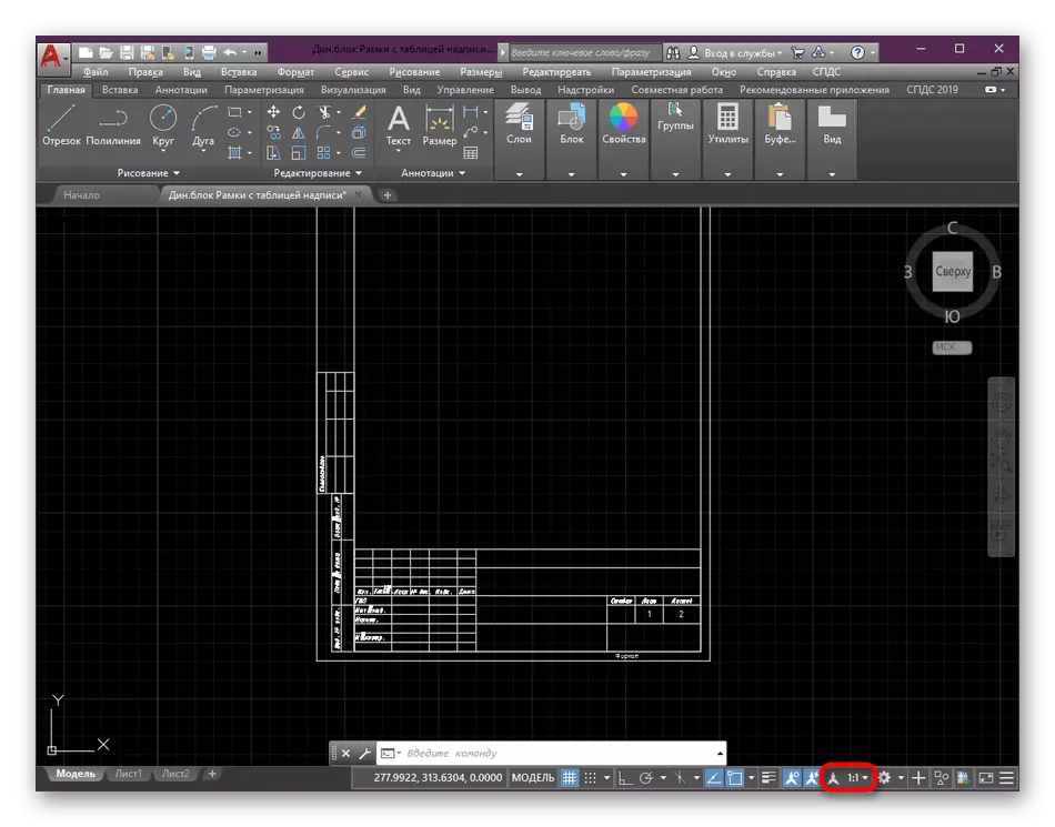
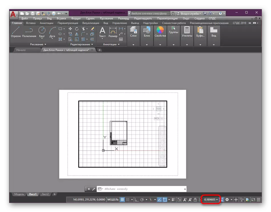
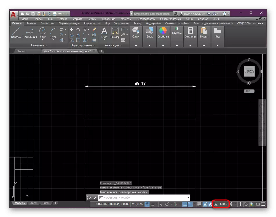
When working on a project in the "Model" section, it is always recommended to use the scale of 1: 1, and already when designing the position and individual parts to adjust it as it is convenient. This approach to work greatly facilitates the execution of certain operations and interaction with the drawing. In the screenshot below you see a button that is just responsible for changing the scale.
Setting the scale of sheet
Previously, we have already said that the scaling is better to exercise after the completion of the work on the main elements of the drawing. This is done in the "Sheet" module by selecting optimal values. You only need to make such actions:
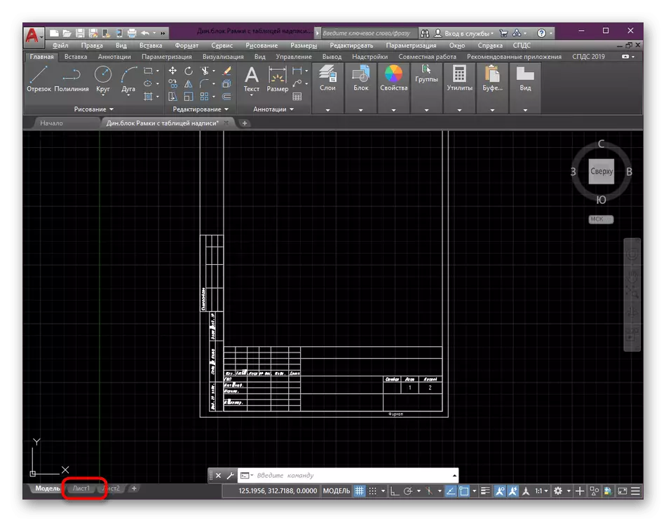
- On the bottom tab of the tabs, locate the required sheet and move to it by clicking on the left mouse button.
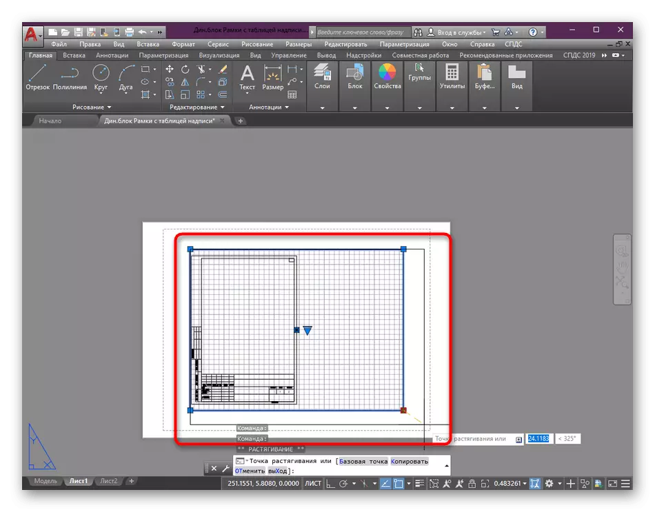
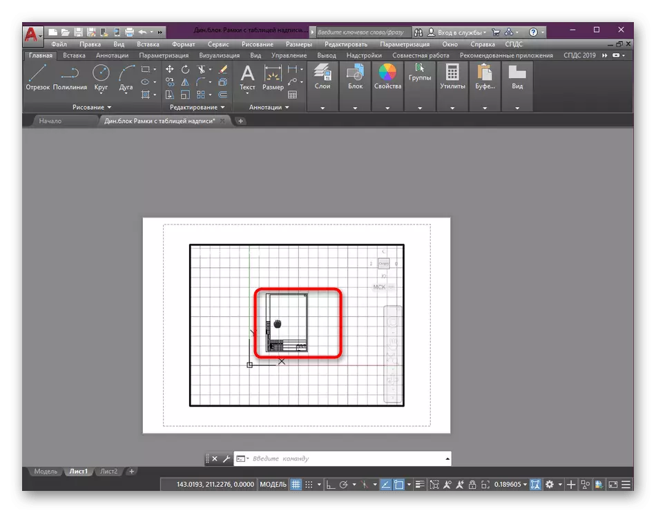
- Initially, do the editing of the viewport. Set the correct size by moving the area.
- Next, select the species screen itself, clicking the LKM twice by its border.
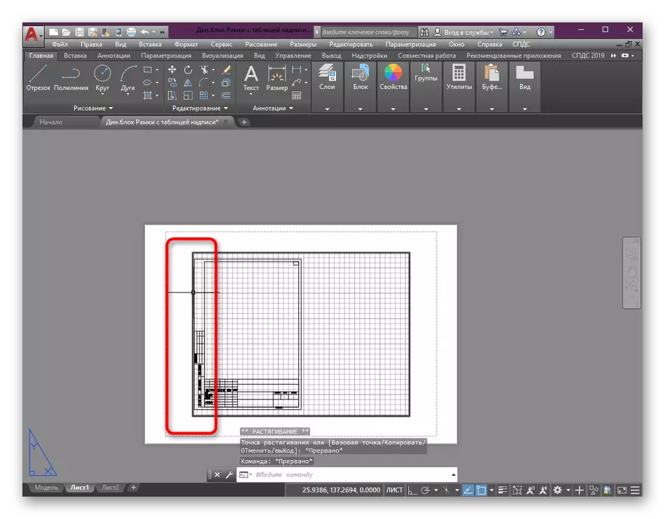
- Here, center the type of drawing by moving it by closing the LKM + the mouse wheel button.
- After that, click on a specially designated scale button.
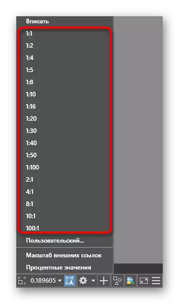
- Select one of the proposed options that are added by default.
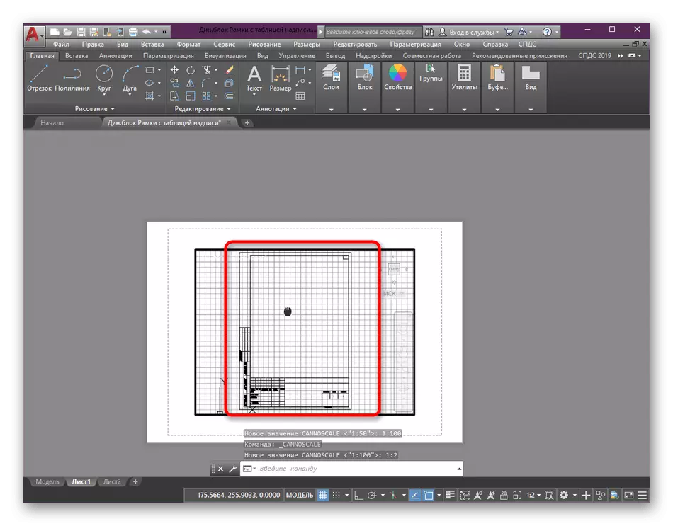
- Now pay attention to the fact that it is no longer recommended to change the size of the drawing in the specimen screen by scrolling the mouse wheel, as it will someteen the setting installed. You can only centen the picture again as it was shown earlier.
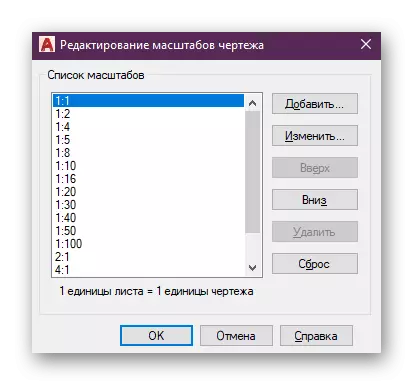
- If necessary, add your own scale option by clicking in the context menu to the "Custom" option.
- In the window that opens, the addition of an unlimited number of suitable scaling options is maintained, all of them will be saved and accessible to the selection even after closing this project.

In one of the disassembled steps, you could see that the species screen was allocated before changing the scale. It is done to designate the area that will change. In addition, several species screens are often used on one sheet, and sometimes it is necessary to pick up each different scale. Consider this when editing. Read more about all the nuances of working with specimen screens in another our material, while moving on the link below.
Read more: Using view screens in AutoCAD
As for additional options, for example, adding a new sheet or design a frame before changing the size of the size, these topics also dedicated separate articles. They present detailed guidelines for all the nuances of interest, as well as instructions on the implementation of basic tasks.
Read more:
Adding and adjusting the frame in AutoCAD
Creating sheets in the AutoCAD program
Print Setup
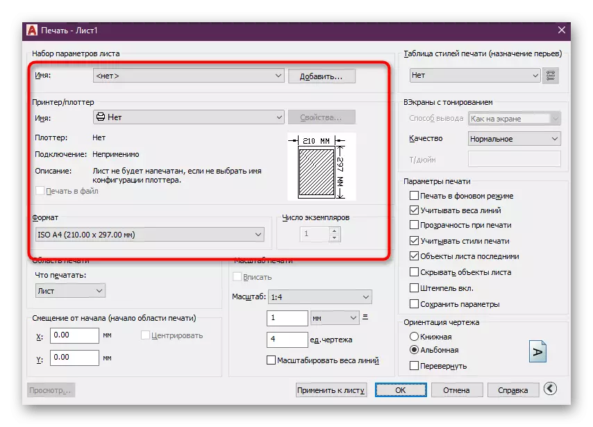
Sometimes some users do not stop for a long time in the species screens and immediately send an existing drawing to print or convert with further preservation in PDF. In such cases, you can set the scale immediately from the print settings window, which looks like this:
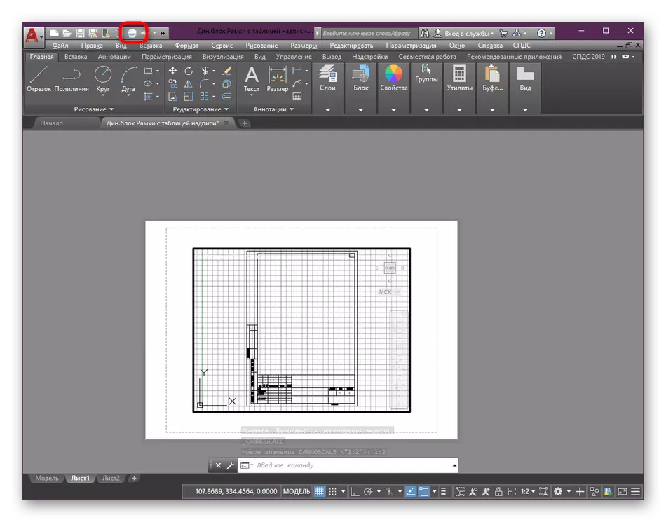
- Find the quick access panel at the top and click on it to the standard printer button to call the required menu. It is done with the Ctrl + P key combination.
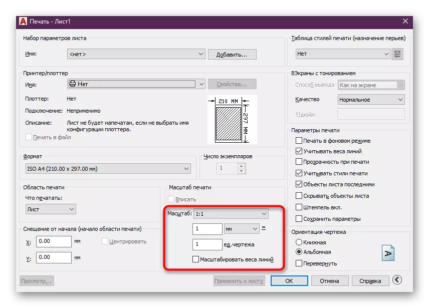
- In the window that opens, move the cursor to the section "Print Scale" and here to set the most suitable parameters for you, given the units of measurement and weight of the lines.
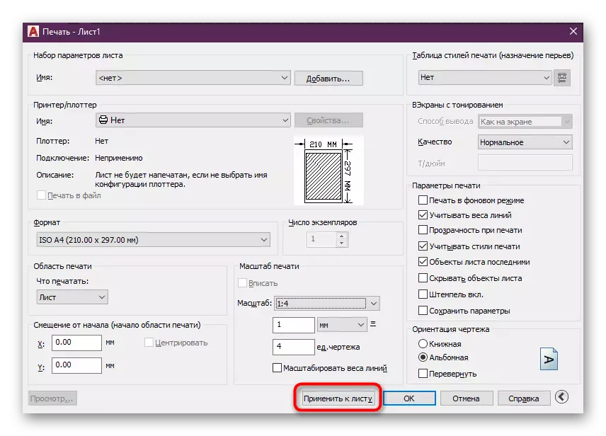
- After that, apply the changes to the sheet to and in the preview mode on the view screen displayed the same result.
- Make the rest of the print configuration and run the task execution.
Above, we just wanted to demonstrate the operation of changing the proportions of sizes without stopping on every detail of the preparation for printing or preserving the project in AutoCAD. You can read about all this without any problems in separate materials, where information is presented as the maximum deployed form.
Read more:
Saving a drawing in PDF format in AutoCAD
How to print a drawing in autocad
AutoCAD: Keep the drawing in JPEG
Annotative size and hatching parameters
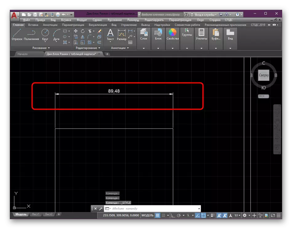
Sometimes, when changing the scale, users encounter problems that are associated with the display of hatching and sizes. The fact is that with the disabled annotation, their ratio will not be completely correct. Therefore, it is recommended to include this parameter to obtain an appropriate look at any scaling. With dimensions it is done like this:
- If you have not created sizes or configured them, do it, and only then go to the next steps.
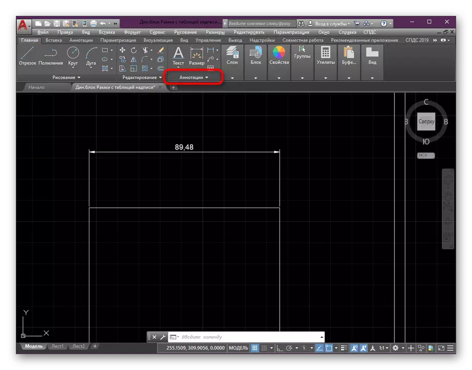
- Expand the details of the "Annotations" section, finding it in the main tape.
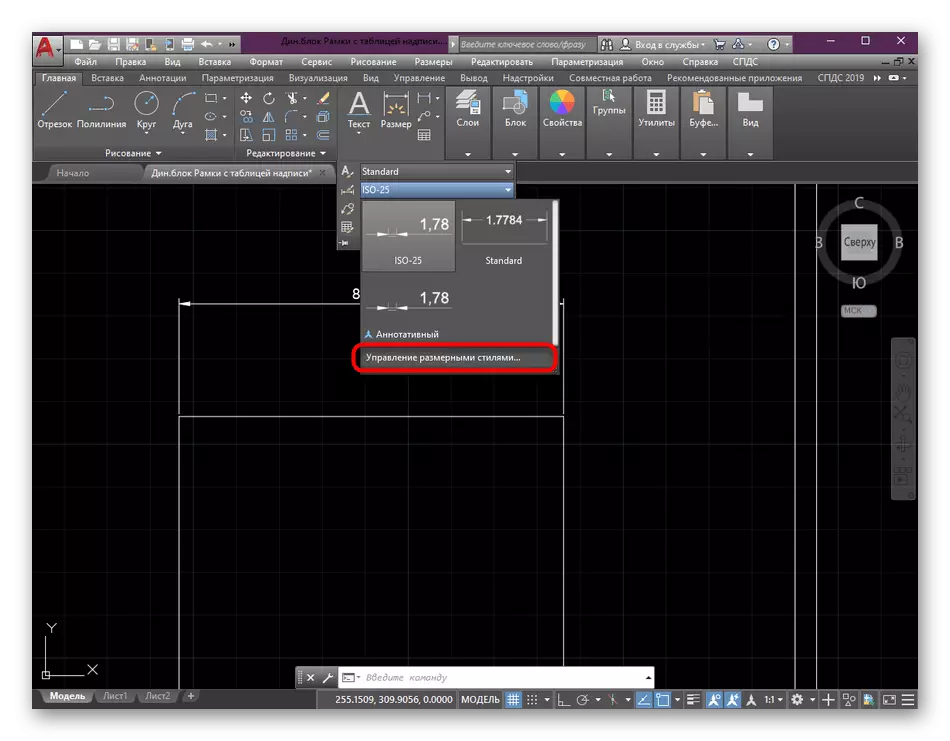
- Here click the "Dimensional Style Management" button.
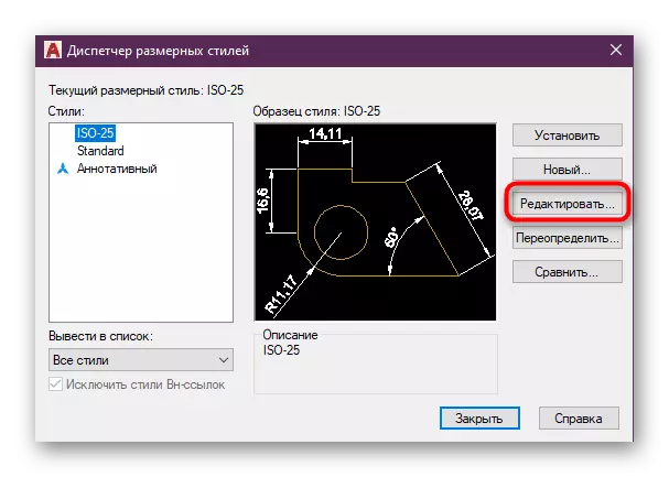
- In the window that appears, select the style used and click on "Edit".
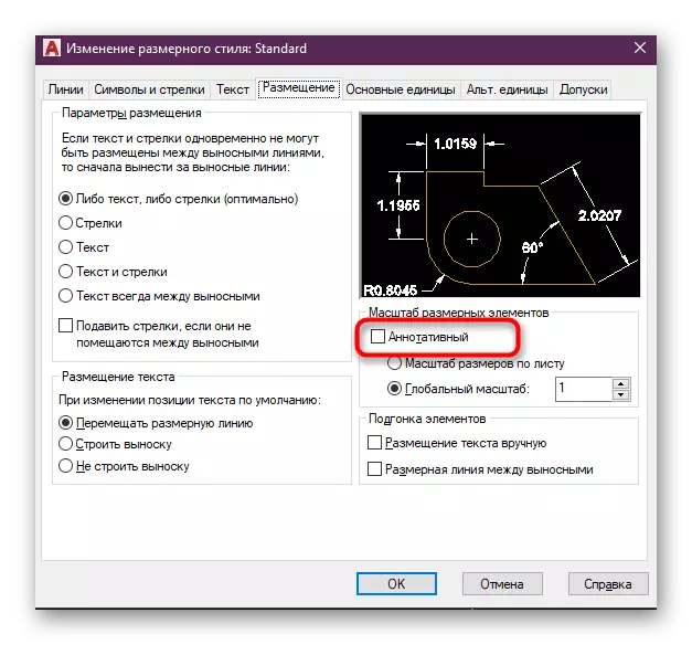
- In the "Placing" tab, enable the "annotative" mode, which is in the category "Scale of Dimensional Elements".
- After that you can change the scale as it will be pleased. The ratio will now always be correct.
In most cases, the implementation of such actions with dimensions and hatching is necessary, since it makes the drawing correct and allows us to interact much easier to interact with various scales and proportions. If you have not mastered the creation of hatching and sizes, make it using special lessons.
Read more:
Creating hatching in AutoCAD
How to put sizes in autocad
When additionally needs any other actions with a drawing, for example, add arrows or objects, do it before changing the scale in a 1: 1 ratio to avoid inaccuracies. We also advise you to learn the training materials on the topic of the car, if you are a novice user.
Read more: Using AutoCAD Program
Now you know everything about changing the scale of drawings in AutoCAD. As you can see, it is best to do after completing the drawing in the design module. In addition, do not forget about the use of annotectivity, because it will help to maintain the correct display of important details, including dynamic blocks.
Read more: Using dynamic blocks in AutoCAD