
During the interaction with the workspace user is faced with the fact that by default all figures in two-dimensional mode are a top view, that is not always necessary when creating certain projects. Because there is a need for changing the display by means of parallel projections. This type of species concepts called axonometry. There are several types of such projections, all of them considered it makes no sense, because today we will focus only on the most popular type - isometric view. Let us examine an example of the projections in the AutoCAD software.
Using the perspective view in AutoCAD
Isometric means that the distortion is equal in all three axes, because this type and is the most popular. However, AutoCAD has a large number of additional settings allow you to customize isometric or other kind of the way it will be most convenient to the user. The same applies to drawing primitives.Immediately clarify small detail - is any type of 2D-perspective drawing which merely simulates a representation in three dimensions. Construction of these projects has nothing to do with 3D-simulation, be sure to consider this before you perform the instructions below. If you want to deal with the three-dimensional modeling and three-dimensional figures, it is advisable to get acquainted with a separate material on this topic by clicking on the link below.
Read more: 3D-modeling in AutoCAD
Changing the drawing mode
If you are just starting out in isometric mode, without creating standard drawings, be sure to change the type of drawing, putting bindings. This will greatly simplify the procedure itself drawing and will display every detail right, in accordance with the coordinate axes.
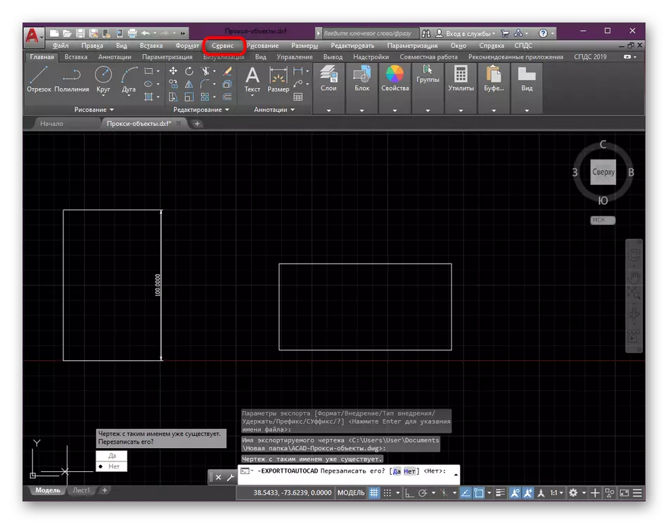
- The top panel in AutoCAD click on the "Tools".
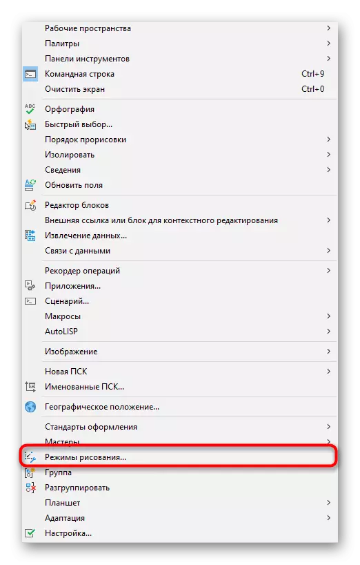
- A new context menu in which you want to move to the "Drafting Settings".
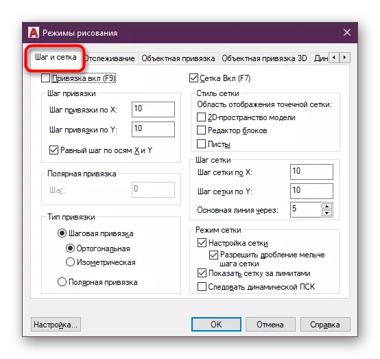
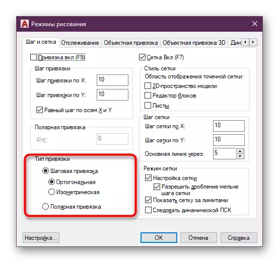
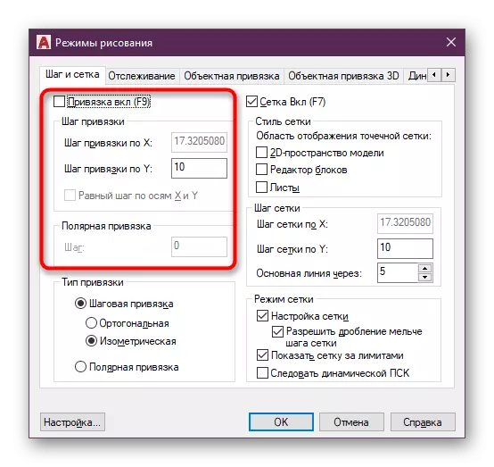
- Make sure that you are in the first tab called "Snap and Grid".
- Here, find the "binding type" and change it to "Isometric". There is also an additional mode "Polar Snap", which we will discuss below.
- Now you can see that a change in the appearance of the map's grid changed immediately, but it is still not fully adjusted.
activation of bindings
Almost no drawing can be built without turning on bindings. Manually close all segments at endpoints will be very difficult, and there is also no warranty that it will do it right. Therefore it is always recommended to include bindings both object and steps on the map, which is happening like this:
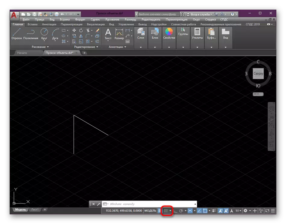
- Lower your view on the status bar, where to click on the arrow near the "Bind" button.
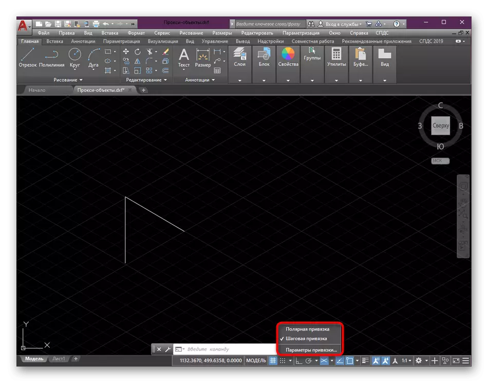
- You can activate step or polar binding. If there is a need to change the length of one step, proceed to the parameters.
- In the window, specify the steps value and activate the binding itself.
- Make sure that the bindings were successfully activated by paying attention to the same icon. It should shone blue.
- After that, when building primitives or figures, the binding will be carried out independently, pushing out from the step, polarity or points of the object.
Now we have touched the topic of bindings only superficially, as it relates little to the current topic. If you have not yet figured out this built-in function, we recommend that it can be done as soon as possible, what will help the learning lesson on our website.
Read more: Using bindings in AutoCAD
Change isometry plane
Total AutoCAD proposes to use one of the three available isometry planes. Each of them will be useful only in certain circumstances. You can independently change the display of the planes using a specially reserved button.
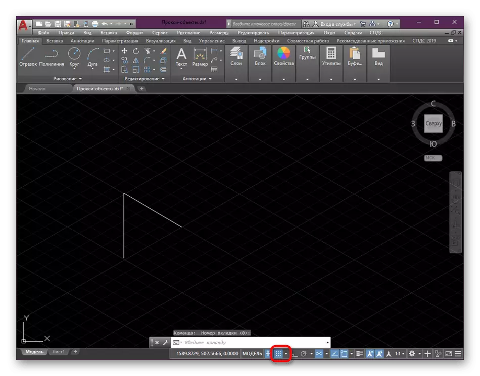
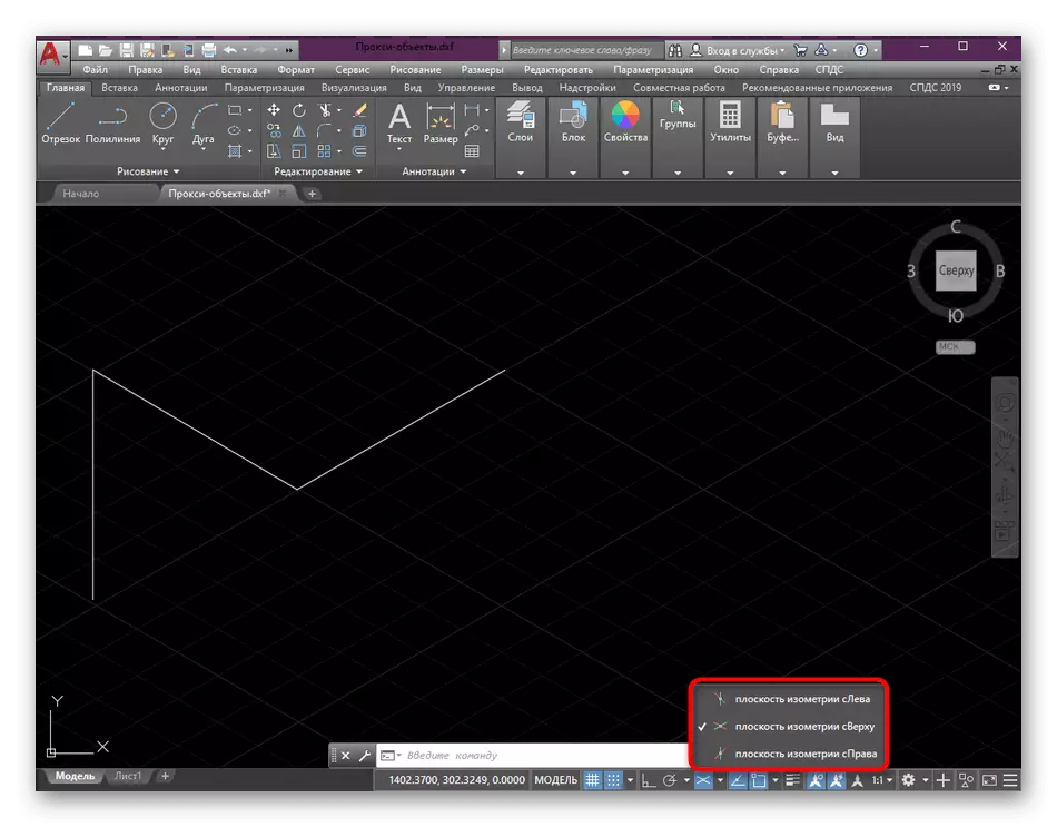
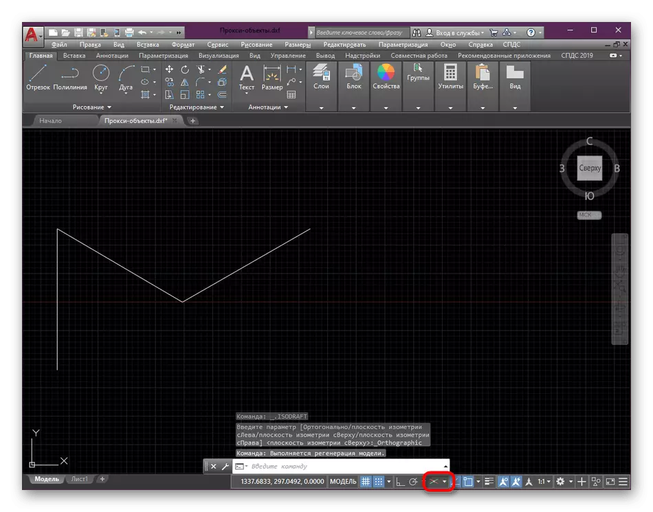
- Pay attention to the status bar, where press the "Isometric Design" button.
- The menu opens with the selection of the view. Here is the "plane of isometry on the left", "plane of isometry from above" and "plane of isometric on the right". You only need to choose the appropriate option, noting it with a check mark.
- If you turn off an isometric view, the drawing will be shown in its standard form.
While working on the project, you can switch between all presented projection modes at any time. However, it should be borne in mind that some of the lines may be hidden from view or shown is not exactly the way it really is.
Drawing in isometric projection
If a drawing in the usual form, everything is clear, that in perspective mode, some users sometimes have different issues. The most important thing here - to use a binding, which we discussed above. Without them, it would be difficult to build the correct figure. For the rest, everything is pretty standard.
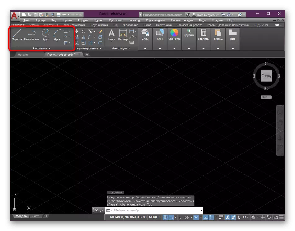
- Select one of the drawing tools on the main stream of the program.
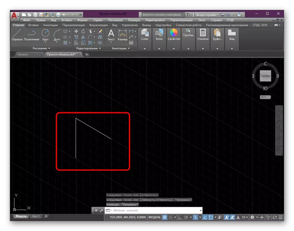
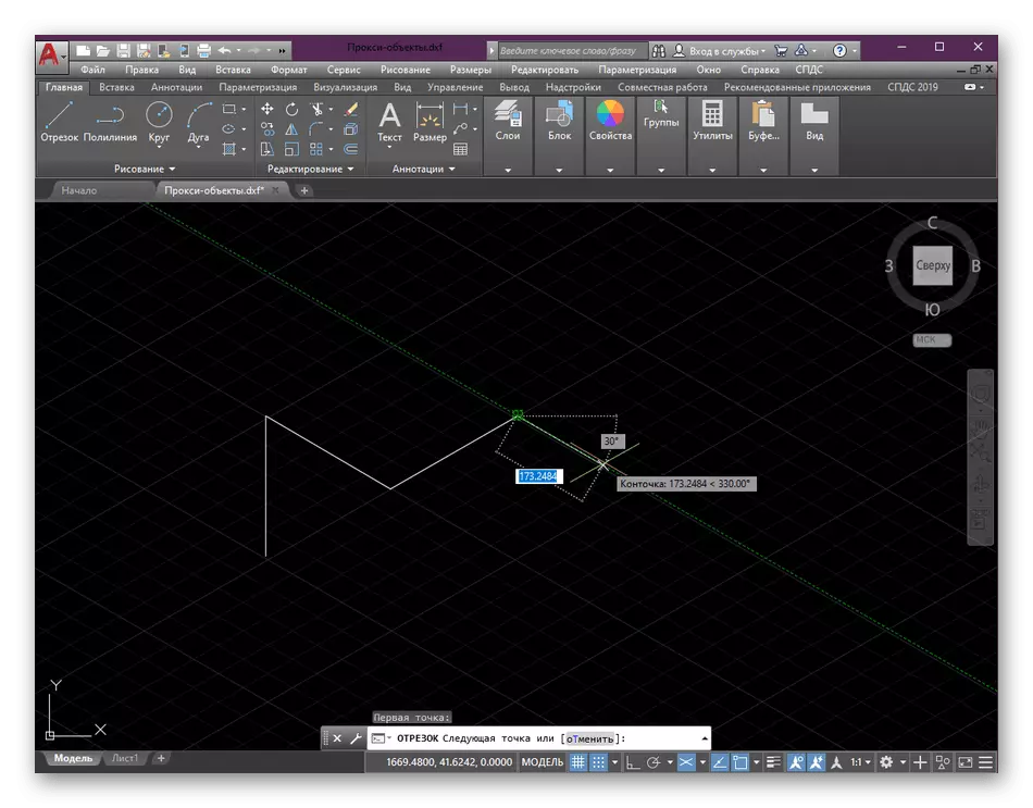
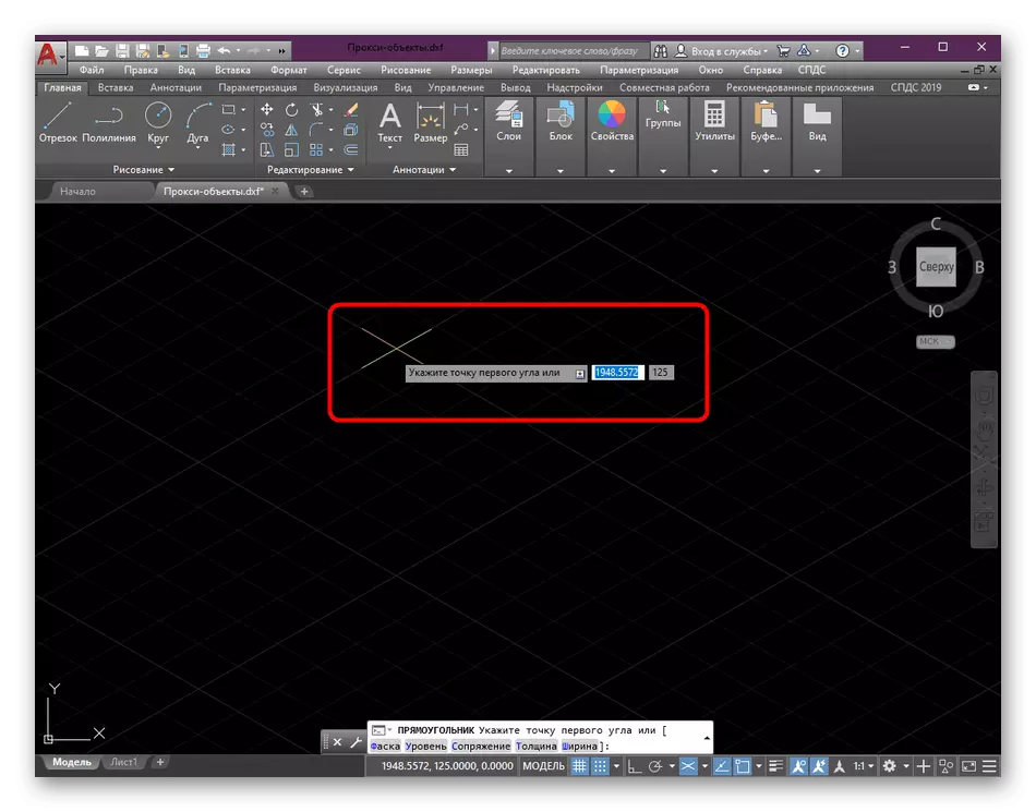
- Start painting from the first point. Note that the cursor display is also different from the previous regime. Now he is on parallel axes.
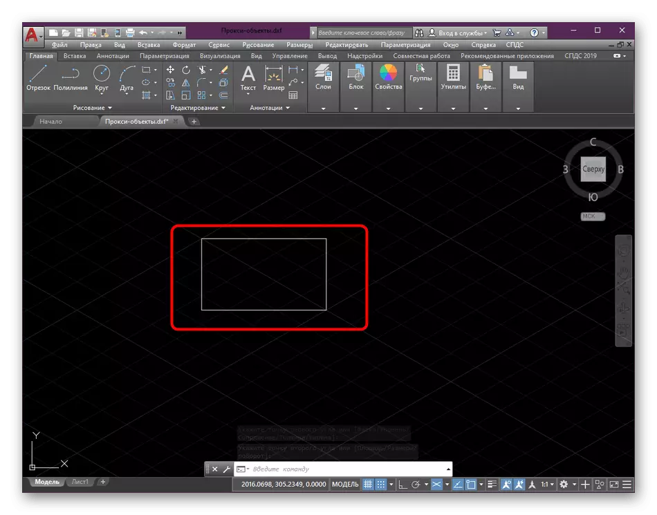
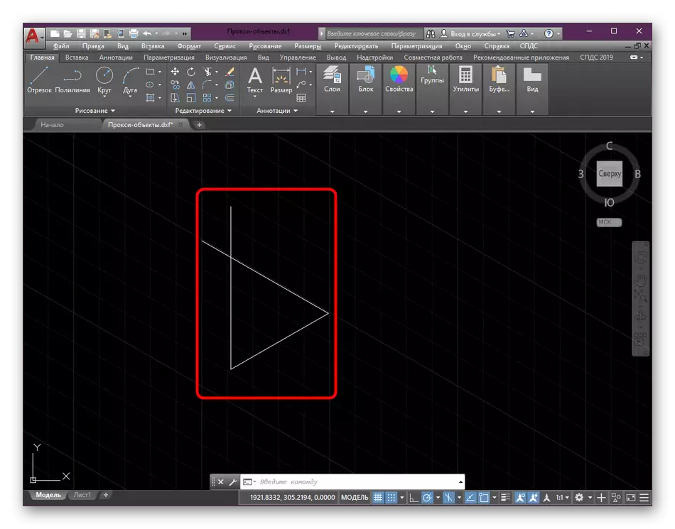
- If you build a standard rectangle, you will see that it is only one point corresponds to the location of the axes, while others are a bit inconsistent.
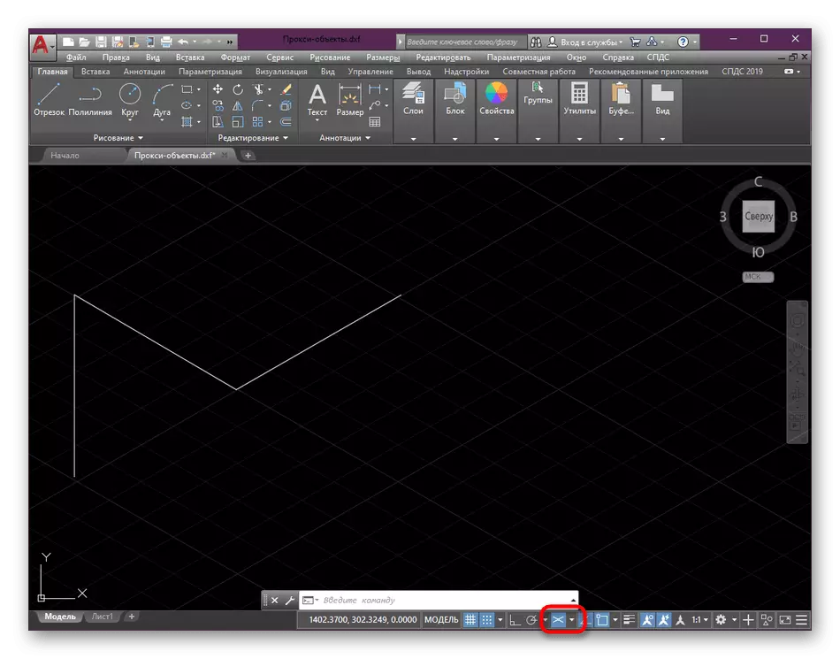
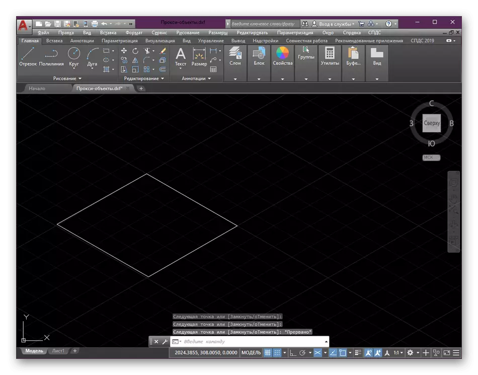
- When constructing line segments or polylines, this problem does not occur because the binding is activated to absolutely every point.
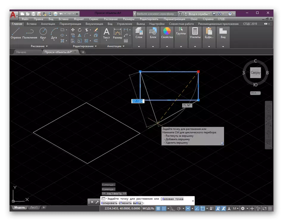
- However, nothing prevents you from immediately after the construction of the rectangle to select a point and move it to the other axis, forming similarity discussed above object of the segments.
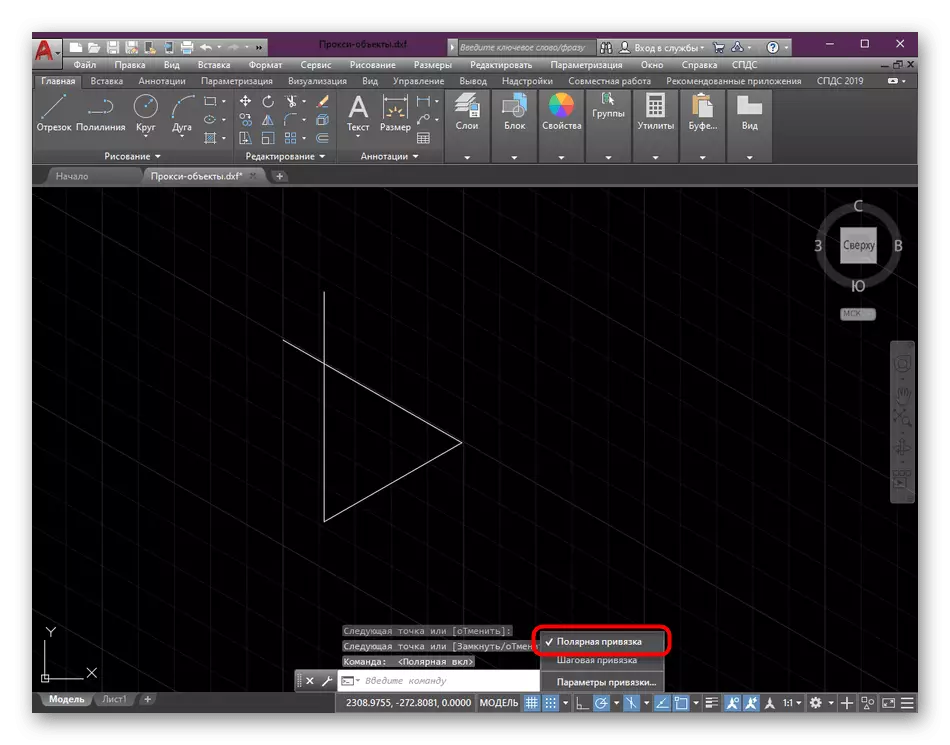
- Selecting "Polar Snap" drawing done a little differently. In it you can make a start it from the coordinate axes.
- All the nuances of such actions only when you understand the construction of handwritten objects in the drawing.
Additionally, we note that in addition to binding to the drawing there is still a huge amount of different details and rules that need to be considered during the creation of primitives, or other similar objects. Detailed guidance on this subject can be found in other material on our website by clicking on the link below.
Read more: Drawing of two-dimensional objects in AutoCAD
Adding dimensions
Drawings created in isometric view, too, often need to set the size. If you are concerned about the fact that these lines will not be displayed correctly or change the principle of their structure, can not worry, everything is done by the usual algorithm:
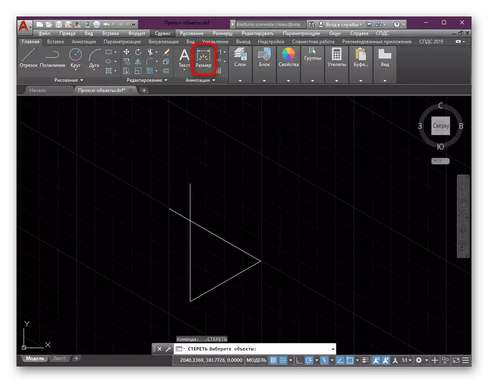
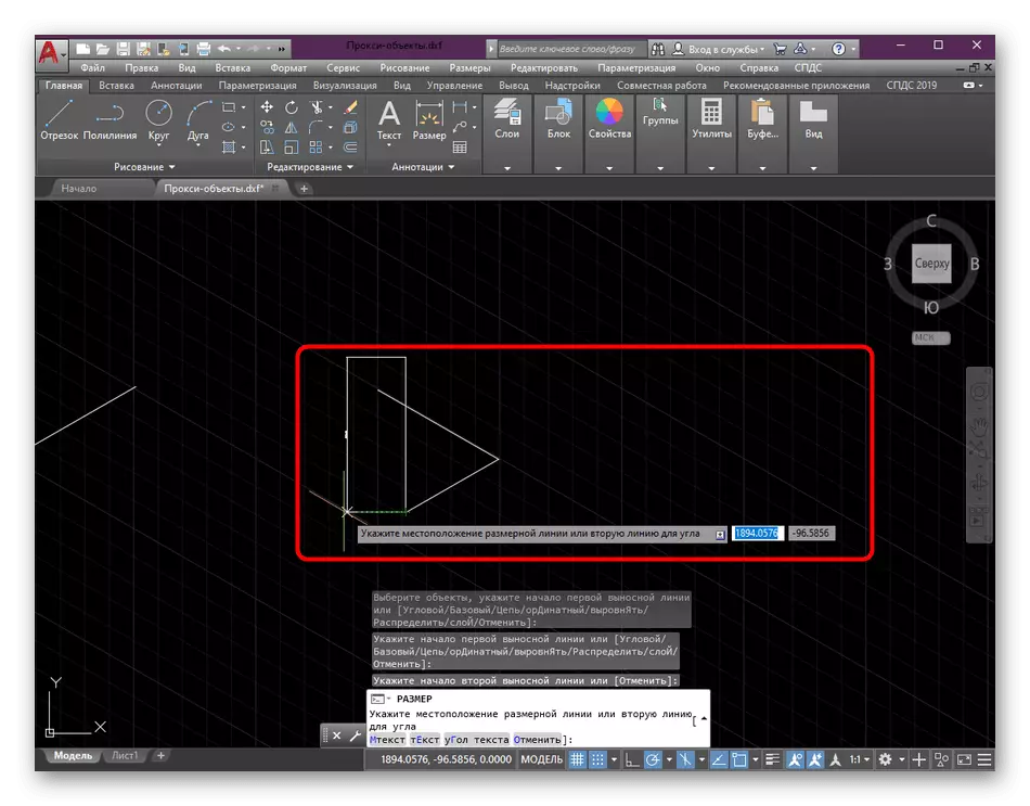
- On the main page of the tape in the "Summary" section, select the tool "Size".
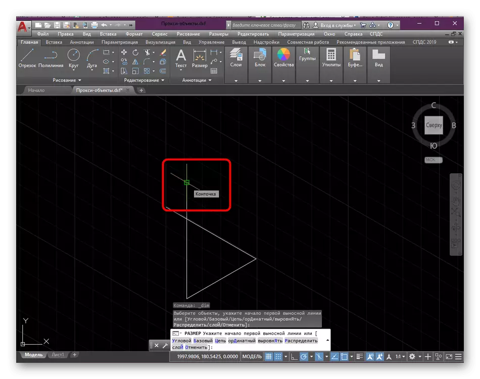
- Define the first point of the dimension line by clicking on the desired segment of the left mouse button.
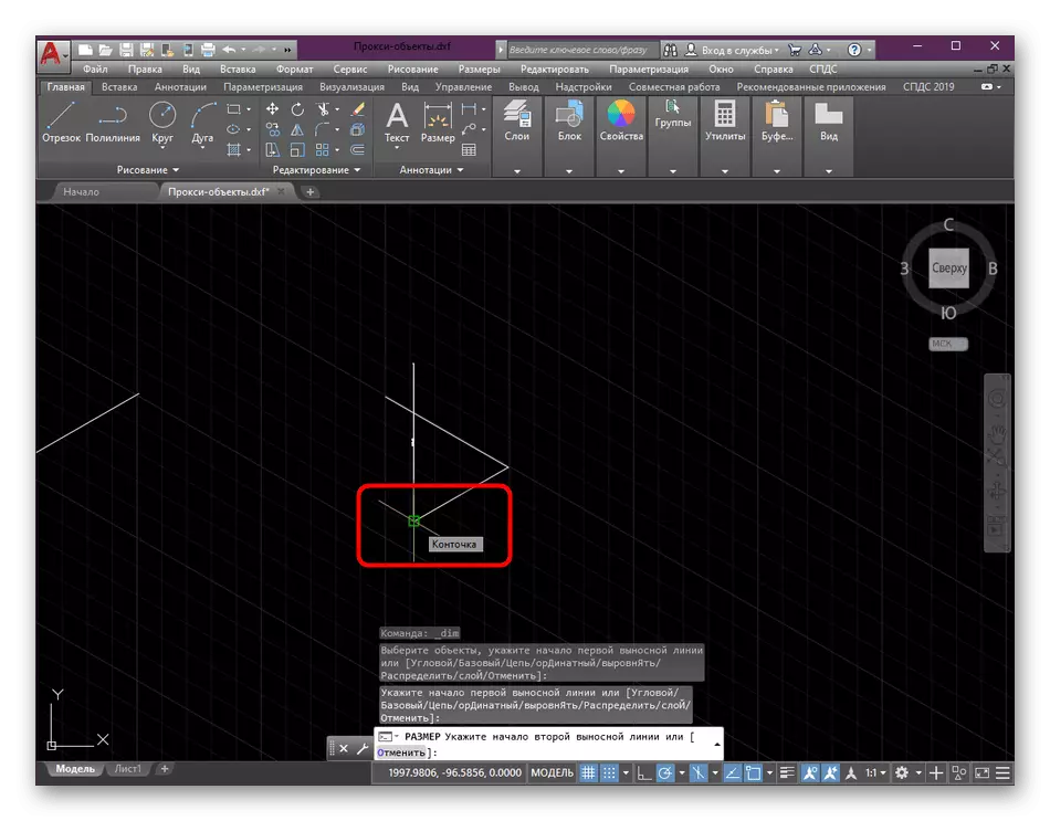
- Spend the line, selecting the end of the same.
- Take out a separate line dimension line that it does not merge with the main object. Then you will see that everything was built correctly and in accordance with the general rules.
The installation dimensions, too, there are certain nuances and additional parameters to be set up and followed for conducting such segments on the project. In addition, the configured lines, arrows, and styles of inscriptions, and be sure to take this into account when creating the working drawing.
Details: Using dimension lines in AutoCAD
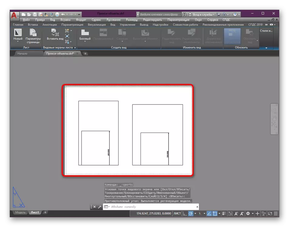
Configure a viewport
Typically isometric projection drawing does not play the main role and is only used to display specific details. Then added to the list of required amount additive viewports where there is display of the same design, but on different sides. In a separate article on our website you will find detailed instructions on the subject, as well as learn all the rules configuration of viewports in the project worksheet formatting.
Read more: Using view screens in AutoCAD
Translation drawing in isometric view
We have considered examples of the settings and change the type in cases where the drawing has not yet been built. It is not suitable for those users who already have some shapes on the map. In this case they will be easier to move in isometric projection, a setting of the coordinate axes. This happens with the help of small manipulations with the properties.
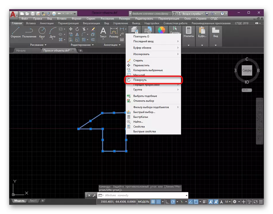
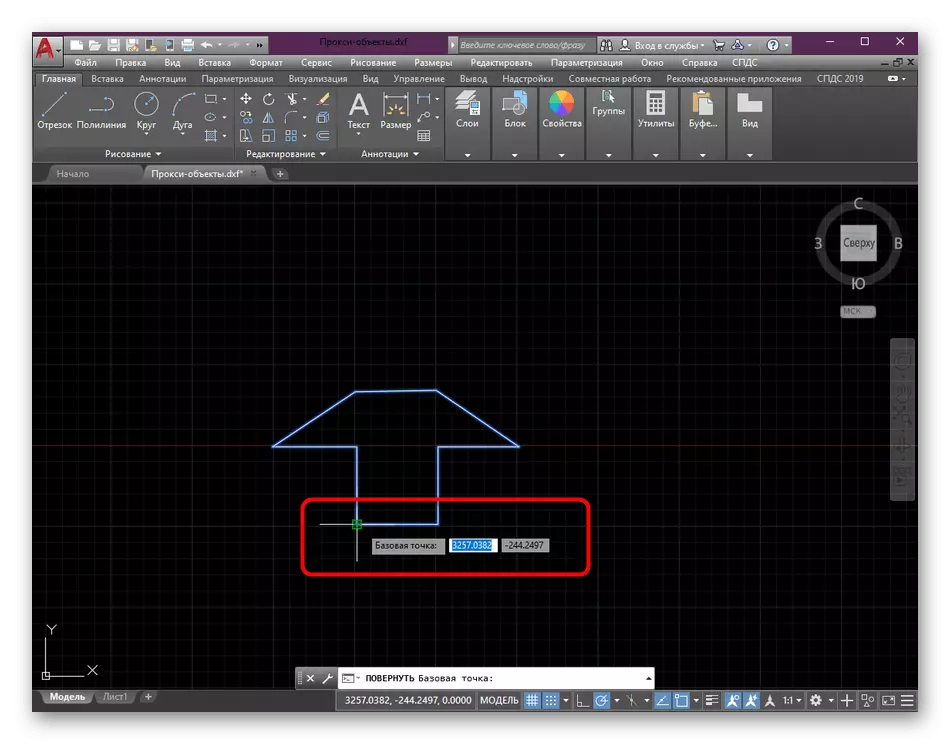
- To start with a standard frame select all points included in the drawing.
- Then click on one of the objects, right-click on the shortcut menu, click "Rotate".
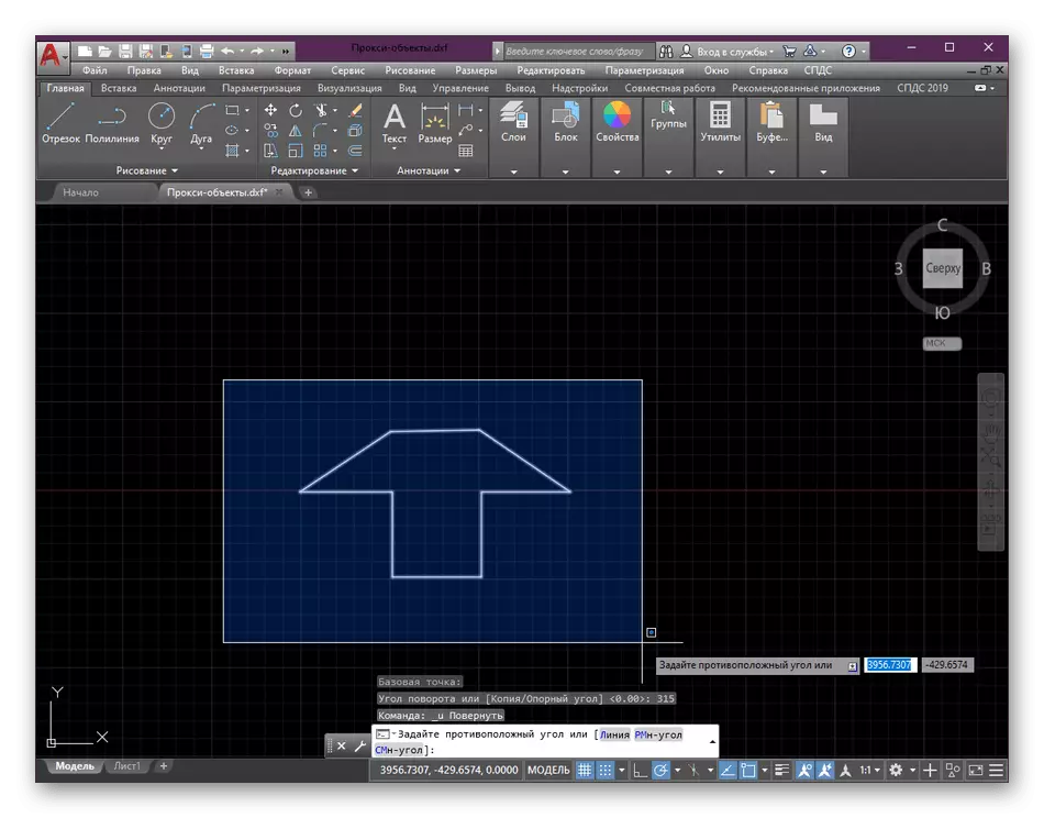
- Specify the base point around which will be rotated.
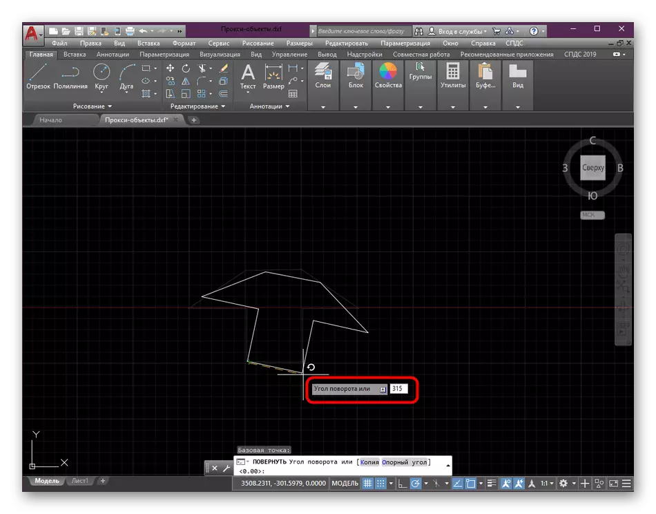
- Then, by entering numbers from the keyboard to specify a rotation angle of 315 degrees.
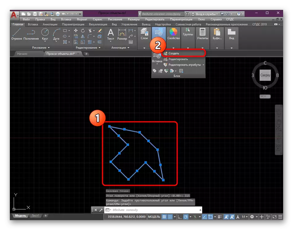
- Groups all elements included in one block. Detailed instructions for the implementation of the task look at other material on.
As for the implementation of other actions - dismembering the block, removal of unnecessary objects, creating polylines and everything else that is part of the usual drawing, now we will not stop on this, since these information is not included in today's article. In addition, they are described in detail in a separate lesson on our website.
Read more: Using AutoCAD Program
As you can see, the use of axonometric projections in AutoCAD is extremely useful. It should be borne in mind that the workspace is capable in every possible way to edit in terms of the view in free mode, so you can always pick up the perfect viewing angle to perform certain tasks.