
On the motherboard there are a huge number of diverse connectors and contacts. Today we want to tell you about their pinout.
The main ports of the motherboard and their pinout
Those present on the "Mothermnel" can be divided into several groups: power connections, connection of external cards, peripheral devices, and coolers, as well as front panel contacts. Consider them in order.Nutrition
Electricity on the motherboard is fed through a power supply that connects through a special connector. In modern types of system boards, there are two types: 20 PIN and 24 PIN. They look like this.
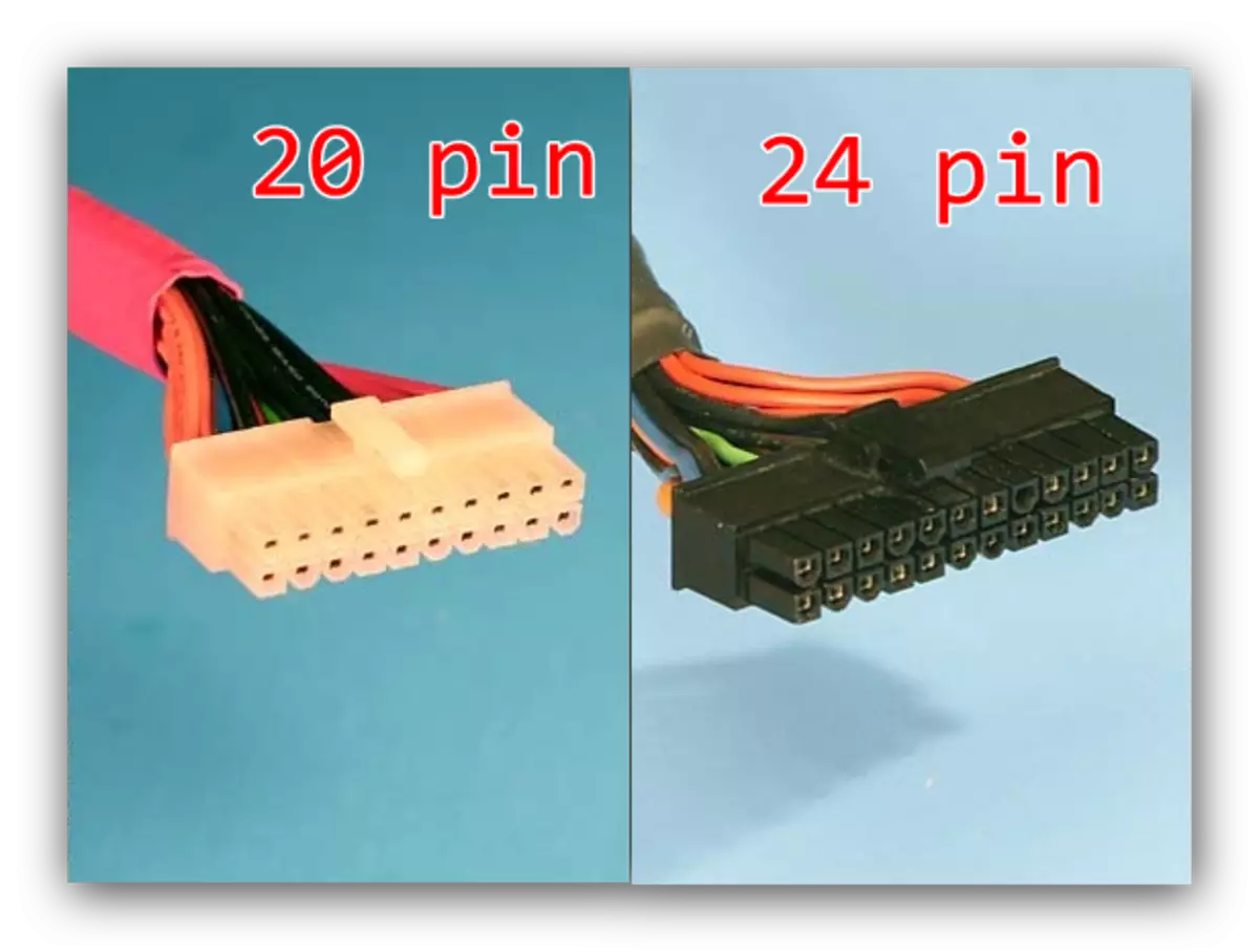
In some cases, each of the main contacts add four more, for compatibility of blocks with different system boards.

The first option is older, it can now be found on the motherboards of the release of the mid-2000s. The second today is relevant, and is applied almost everywhere. The pinout of this connector looks like this.

By the way, the closure of PS-ON and COM contacts can be checked the performance of the power supply.
See also:
Connecting the power supply to the motherboard
How to turn on the power supply without motherboard
Peripherals and external devices
Connectors for the periphery and external devices include contacts for hard disk, ports for external maps (video, audio and network), LPT and COM type inputs, and USB and PS / 2.
HDD
The main connector used now for the hard disk - SATA (Serial ATA), but at most motherboards there is also an IDE port. The main difference between these contacts is the speed: the first is noticeably faster, but the second wins due to compatibility. Connectors are easy to distinguish in appearance - they look like this.

The pinout of each of the specified ports is different. This is how the IDE pinout looks like.

And so SATA.

In addition to these options, in some cases, the input of the SCSI type can be used to connect the periphery, however, at home computers, it is a rarity. In addition, most modern optical and magnetic drive drives also use data types of connectors. About how to connect them correctly, we will talk another time.
External cards
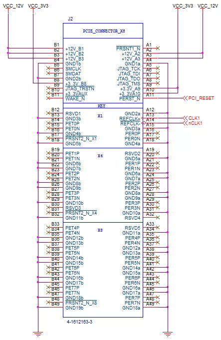
To date, the main connector for connecting external cards is PCI-E. Sound boards, GPUs, network cards, as well as diagnostic post-card are suitable for this port. The pinout of this connector looks like this.
Peripheral slots
The oldest ports for the connected failures are LPT and COM (otherwise sequential and parallel ports). Both types are considered already obsolete, but still apply, for example, to connect old equipment, replaced which is not possible to modern analogue. Pickup data connectors looks like this.

Keyboards and mice are connected to PS / 2 ports. This standard is also considered obsolete, and is massively replaced with a more relevant USB, but PS / 2 provides more opportunities to connect control devices without the participation of the operating system, therefore in the go. The diagram of contacts of this port looks like this.

Please note that the inputs for the keyboard and mouse are strictly delimited!
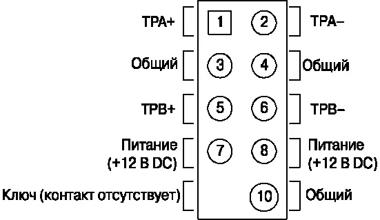
The representative of another type of connector is FireWire, it is IEEE 1394. This type of contact is a kind of UNIVERSAL SERIES Bus and is used to connect some specific multimedia devices like video cameras or DVD players. On modern motherboards, he is rare, but just in case we will show you his pickup.
Attention! Despite the external similarity, USB and FireWire ports are incompatible!
USB today is the most convenient and popular connector for connecting peripheral devices, ranging from flash drives and ending with external digital-analog converters. As a rule, on the motherboard is present from 2 to 4 ports of this type with the possibility of increasing their quantity by connecting the front panel (about it below). The dominant type of YUSB is now type A 2.0, however, gradually manufacturers go to Standard 3.0, which differs from the previous version of the contacts.

Front Panel
The mansion is the contacts for connecting the front panel: output to the front part of the system unit of some ports (for example, linear output or 3.5 mini-jack). The connection procedure and pinout contacts are already reviewed on our website.
Lesson: Connect the front panel to the motherboard
Conclusion
We looked at the pinout of the most important contacts on the motherboard. Summing up, we note that the information set out in the article is enough for an ordinary user.