
The motherboard is in each computer and is one of its main components. Other internal and external components are connected to it, forming one entire system. The above-mentioned component is a set of chips and various connectors located on one palette and interconnected. Today we will talk about the main details of the motherboard.
See also: Choose your motherboard for a computer
Computer motherboard components
Almost every user is clear the role of motherboard in a PC, however, there are facts that are not known about. We recommend to familiarize yourself with the other of our article by reference below to study this topic in detail, and we go to the analysis of the components.Read more: The role of motherboard in the computer
Chipset
Starting with a binder element - chipset. Its structure is two species that vary by the interconnection of bridges. The North and South Bridge can go separately or be combined into one system. Each of them has a variety of controllers on board, for example, the southern bridge ensures the relationship of the peripheral equipment, contains hard drive controllers. The North Bridge acts as a combining element of the processor, a graphic card, RAM and objects under the control of a southern bridge.

Above, we gave a link to the article "How to choose a motherboard." In it, you can familiarize yourself with the modifications and differences of chipsets from popular component manufacturers.
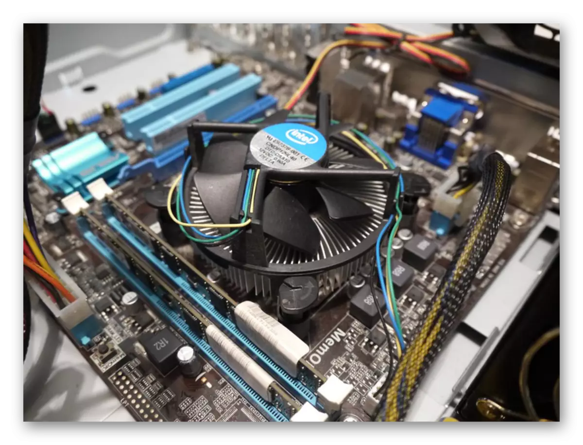
Processor socket
A processor socket is called a connector, which is actually installed this component. Now the main manufacturers of the CPU are AMD and Intel, each of which has developed unique sockets, therefore the model of the motherboard and is selected based on the selected CPU. As for the connector itself, it is a small square with a multitude of contacts. From above the nest is covered with a metal plate with a holder - it helps the processor to stick in the nest.

See also: Installing the processor on the motherboard
Usually, the CPU_FAN socket is located next to connecting the cooler power, and on the board itself there are four holes for its installation.
See also: Installation and removal of the processor cooler
There are many kinds of sockets, many of them are incompatible with each other, since they have different contacts and form factor. About how to find out this feature, read in our other materials on the links below.
Read more:
We learn a processor socket
Learning the mother map socket
PCI and PCI Express
The PCI abbreviation is literally decrypted and translated as the relationship of the peripheral components. This name received the corresponding bus on the computer system board. Its main purpose is to enter and output information. There are several PCI modifications, each of them differs in peak throughput, voltage and form factor. Connect to such connections of TV tuners, audio cards, SATA adapters, modems and old video cards. PCI-Express only uses the PCI software model, but is a newer development designed to connect a plurality of more complex devices. Depending on the mold factor of the socket to it, video cards, SSD drives, wireless network adapters, professional sound cards and much more are connected to it.
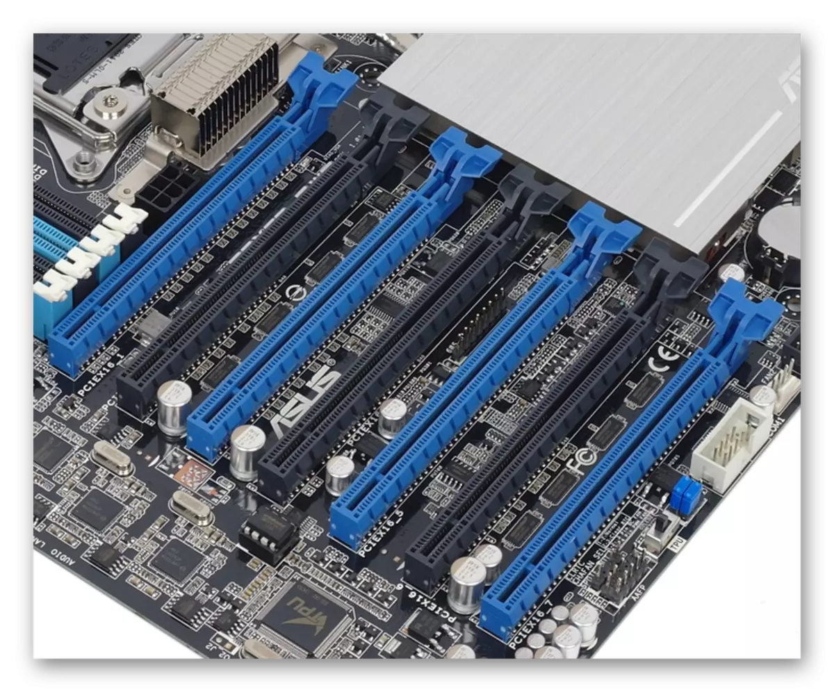
The number of PCI and PCI-E connectors on motherboards varies. When it is selected, you need to pay attention to the description to make sure that the necessary slots are available.
See also:
Connect the video card to the PC motherboard
Choose a video card under the motherboard
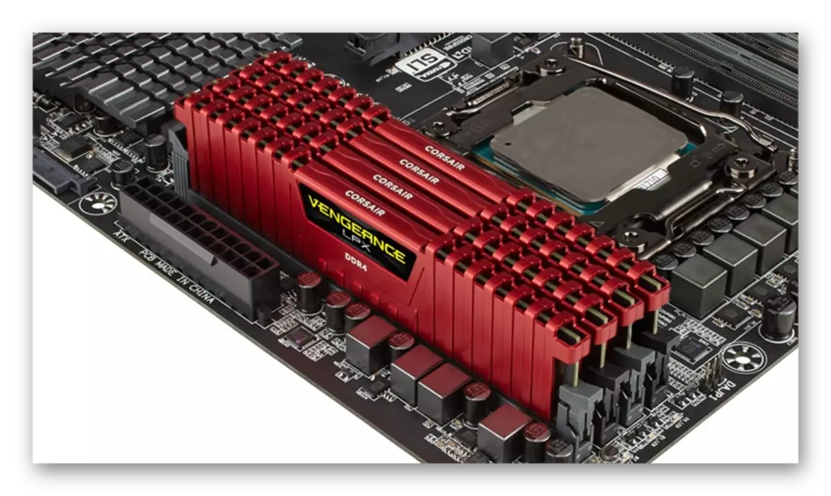
Connectors under the RAM
Slots for installing RAM are called DIMM. In all modern system boards, this form factor is used. There are several kinds of varieties, they differ in the number of contacts and incompatible with each other. The more contacts, the newer the RAM is installed in such a connector. Currently, the DDR4 modification is relevant. As in the case of PCI, the number of DIMM slots on the patterns of the motherboard is different. Most often options with two or four connectors, which allows you to work in two- or four-channel mode.
See also:
Install RAM modules
Check the compatibility of RAM and motherboard
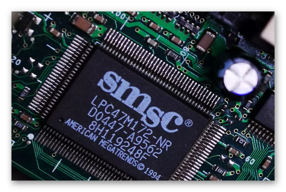
Microcircuit BIOS.
Most users are familiar with the BIOS. However, if you first hear about such a thing, we recommend you to familiarize yourself with the other material on this topic, which you will find at the following link.
Read more: What is BIOS
The BIOS code is located on a separate chip, which is attached to the motherboard. It is called EEPROM. This type of memory supports reusable erasing and data record, however, has a sufficiently small container. In the screenshot below you see what the BIOS chip on the motherboard looks like.
In addition, the value of the BIOS parameters is stored in a dynamic memory chip called CMOS. It also records certain computer configurations. This element feeds through a separate battery, the replacement of which leads to the reset of the BIOS settings to the factory.
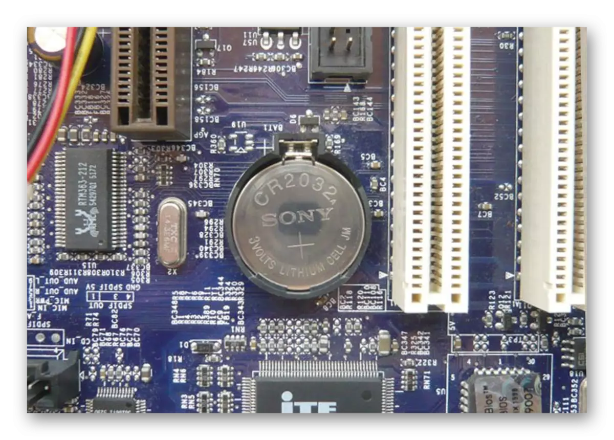
READ ALSO: Replacing the battery on the motherboard
SATA and IDE connectors
Previously, hard drives and optical drives connected to a computer using the IDE (ATA) interface located on the motherboard.

See also: Connecting a drive to the motherboard
Now more common are SATA connectors of different audit, which differ in each other mainly by the transfer rate. The interfaces under consideration are used to connect information drives (HDD or SSD). When selecting components, it is important to consider the number of such ports on the motherboard, since they can be from two pieces and above.

See also:
Methods for connecting a second hard disk to a computer
Connect SSD to a computer or laptop
Power connectors
In addition to a variety of slots on the component under consideration there are various connectors for connecting power. The most massive of all is the port of the motherboard itself. The cable from the power supply is sticking there, providing correct electricity flow for all other components.

Read more: Connect the power supply to the motherboard
All computers are located in the housing, which also contain different buttons, indicators and connectors. Their nutrition connects through separate contacts for Front Panel.

READ ALSO: Connecting the front panel to the motherboard
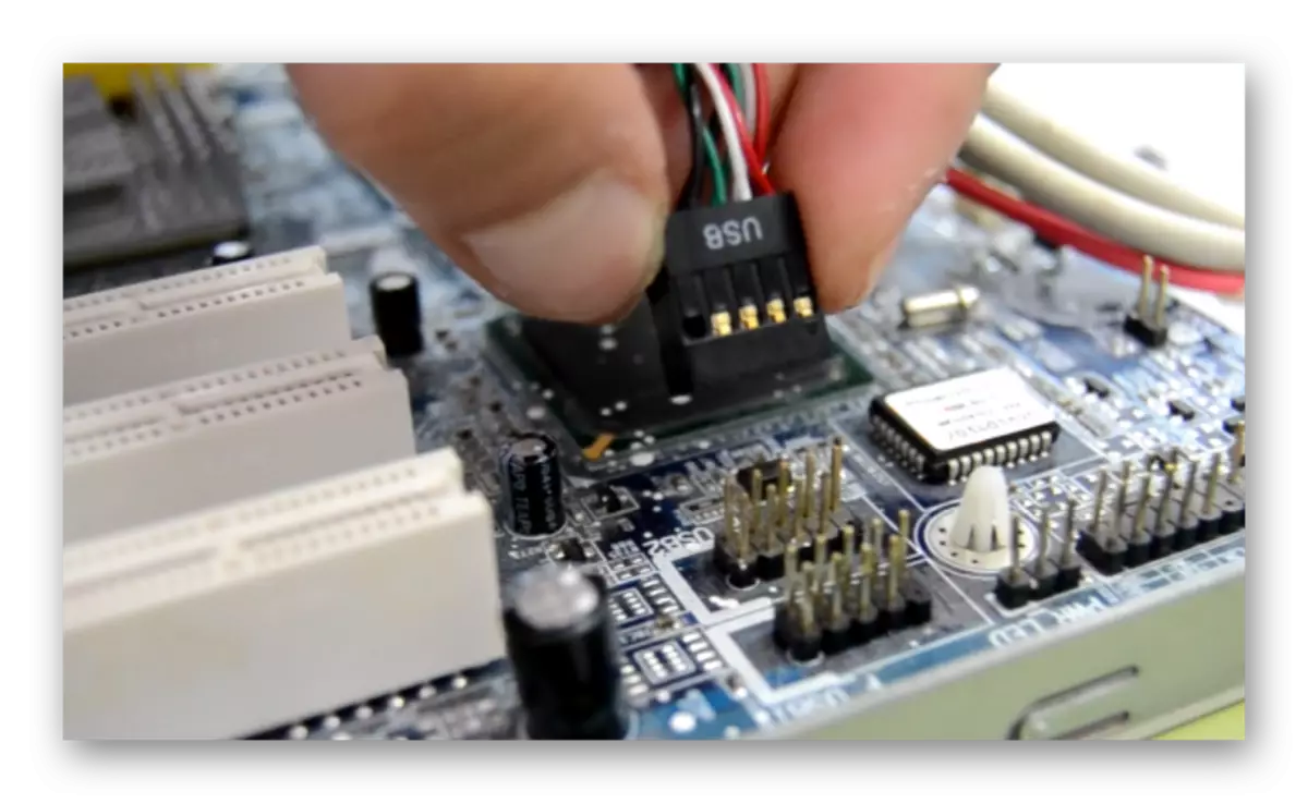
USB interface jacks are separately displayed. Usually they have nine or ten contacts. Connect them may vary, so carefully study the instructions before starting the assembly.
See also:
Picking Motherboard Connector
Contacts PWR_FAN on the motherboard
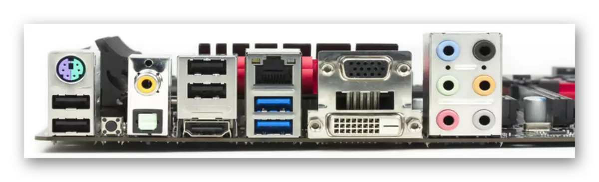
External interfaces
All peripheral computer equipment is connected to the system board by means of specially designated connectors. On the sidebar of the motherboard, you can watch USB interfaces, serial port, VGA, Ethernet network port, acoustic output and input, where the cable from the microphone, headphones and speakers is inserted. On each model of the component, the connector set is different.
We examined in detail the main components of the motherboard. As you can see, there are many slots, microcircuits and connectors for powering, internal components and peripheral equipment. We hope the information provided above helped you understand the structure of this PC component.
See also:
What to do if the motherboard does not start
Turn on your motherboard without a button
Major motherboards malfunctions
Instructions for replacing capacitors on the motherboard