
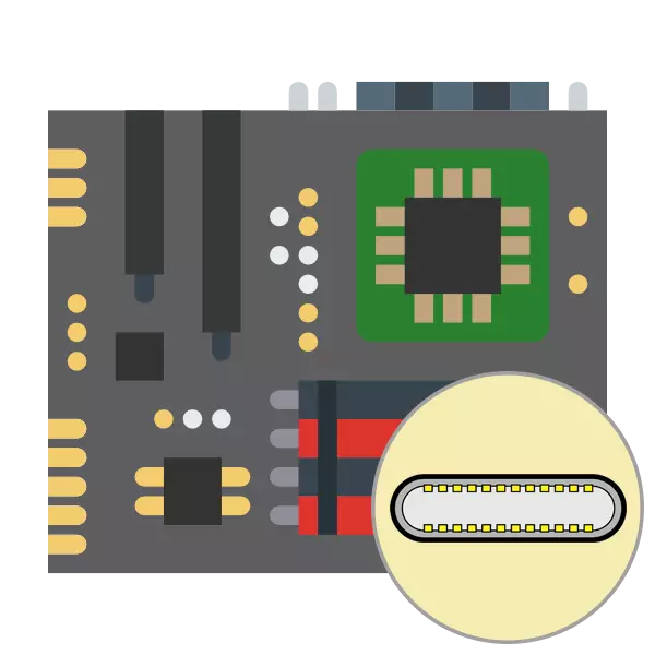
As you know, there are many a variety of connectors on the computer's motherboard for connecting peripheral and embedded components. Among all ports are USB 2.0 and USB 3.0, which serve the signal and power supply from the built-in connectors. These two versions differ not only by technical characteristics, but also views of the ports on the motherboard. In today's article, we would like to disassemble them in more detail.
See also: What makes the motherboard
Pointing of USB 2.0 and USB 3.0 connectors on the motherboard
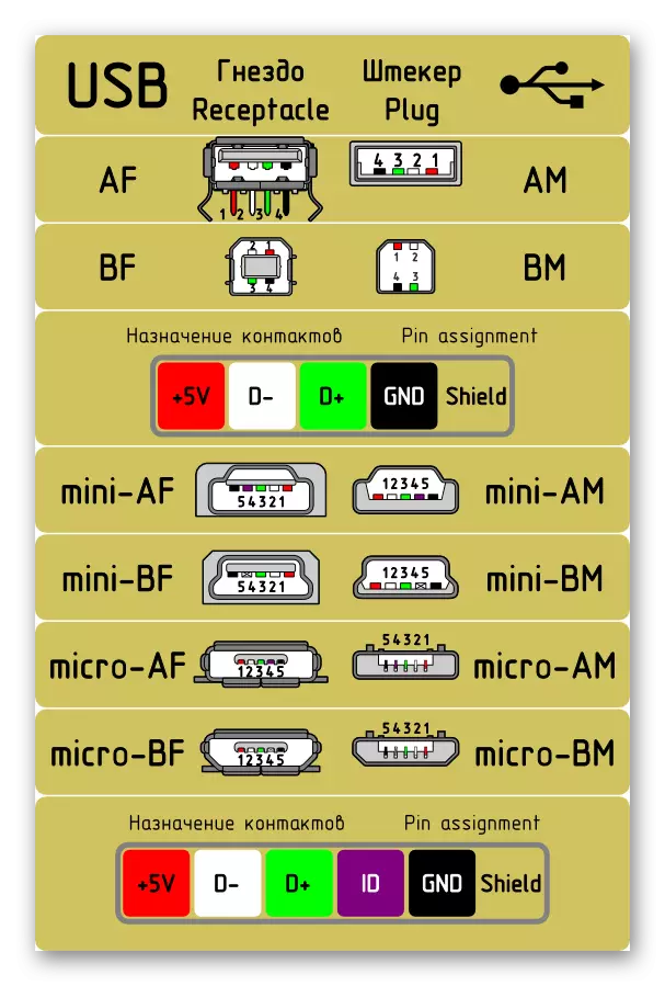
Unfortunately, there is no single designation of all legs and contacts of the connectors, since the technology of their production is not standardized. As a result, the ratio may be different on each model of the motherboard. In the image below, you see a schematic pinout of a USB plug with color designation of each contact. It is from these conventional signs that we will be repelled with the further analysis of the connectors on the motherboard.
USB 2.0
Let's start with a more common USB 2.0. Not all component manufacturers install new USB 3.0 or 3.1 connectors to their boards, but several inputs of the old version 2.0 must be available on board. The pinout looks simple, because the element is only ten wiring or metal legs. Pay attention to the illustration below. There is a conditional designation of all these contacts.

Now let's take turns in turn with each of them so that novice users do not have difficulty understanding the designations:
- 1 and 2. are red and have 5V, VCC or POWER names. Responsible for the supply of power;
- 3 and 4. Allocated with white and almost everywhere are indicated as D- - contacts for data transfer with a negative charge;
- 5 and 6. Green color, symbolic name D + - contact contacts with a positive charge;
- 7, 8 and 10. Usually, the earth is distinguished in black, and the name on contact corresponds to GND.
You could notice the absence of ninth contact. It is not, since this place serves as a key to the concept of properly connecting the wires to the connector.
After familiarizing with the compliance of all contacts, you can only connect wires to them, given all the labeling shown. At the same time, polarity should be observed, because it is not in vain, it is also indicated in schematic drawings.
USB 3.0.
The type of USB 3.0 connectors is modern, and more and less new motherboards have several such built-in ports, which are also connected through the contacts specifically allocated for this. The structure of this port is more complicated, since version 3.0 has more advanced technical characteristics and supports new technologies.
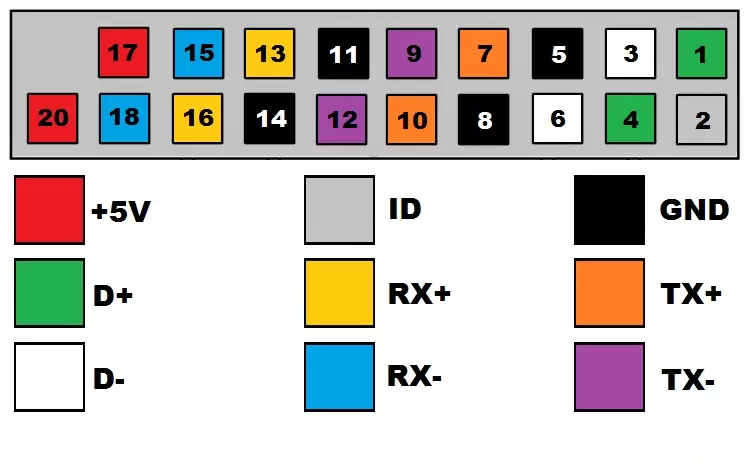
Above you saw a schematic pinout of the connector 3.0, it remains only to disassemble all contacts in a text version:
- 2. The new contact responsible for identification is usually shown by gray and has a symbolic name id;
- 1 and 4. INTA_P2_D + and INTA_P1_D +, respectively. Already familiar pins for data transfer with a positive charge;
- 3 and 6. INTA_P2_D- and INTA_P1_D-. Highlighted wire transmission wires with a negative charge;
- 5 and 8. Earth, as usual, is marked with gray and written GND;
- 7 and 10. Another contact with the plus sign for data transmission through TX. 7 has the name inta_p2_sstx +, and number 10 - inta_p1_sstx +;
- 9 and 12. The same, but with the "minus" sign and the notation of INTA_P2_SSTX- and INTA_P1_SSTX-;
- 11 and 14. Earth;
- 13 and 16. Obtaining RX data with a positive charge and the name of INTA_P2_SSRX + and INTA_P1_SSRX +;
- 15 and 18. RX CE is a minus sign. Names - inta_p2_ssrx and inta_p1_ssrx-;
- 17 and 20. Marked in red and are responsible for supplying power. Have a symbolic designation VBUS.
As in the case of the previous connector, one contact is absent, and this empty place acts as a key. In this option, no room is nineteen. In addition, you could see the addition of new contacts to transmit RX and TX data. This steam is used when displaying and entering information on a serial interface and is now standard in similar schemes.
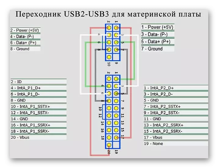
Adapter with USB 2.0 by 3.0
Above you have been familiar with the pinout of all contacts and the detailed description of each of them. Now we want to present a small schematic illustration of the users who are interested in connecting or creating an adapter with USB 2.0 to 3.0. We will not paint in detail the principle of creating such a chain, as this is a topic of a separate article. However, the image below will be a visual aid and help experienced electricians in creating a new connection scheme.
As part of this material, we considered the deployment of the USB connector on the motherboard. If you are interested in a similar analysis of other computer components, we advise you to read individual articles on the following links.
See also:
Solding 3-Pin Cooler
Solding 4-Pin Cooler
Picking Motherboard Connector