
Now printers are very popular with users of different categories. Canon is one of the most famous manufacturers of printing equipment and scanners, which won the market with a huge number of models of various series and price categories. Therefore, we would like to submit a universal instruction in which the procedure for the complete disassembly of printers of this company is as described as in detail, to further perform other actions, such as replacing or repairing components.
We disassemble the printer from Canon
In today's task, there is nothing complicated, the main thing is to find a suitable screwdriver and show accuracy to accidentally do not damage the important components. As for the structure of different models, almost all of them are fulfilled according to one principle and have a similar design. However, if the discrepancies are detected with the following manual, read the instructions that are included in the set, where to find information about the removal of panels or components.Step 1: Preparation for full disassembly
Before starting disassembly, it is necessary to dismantle the main parts - the cartridge, the roller of the capture and the braking area. Only after that it will be possible to access the device inside and unscrew all the other parts without any problems.
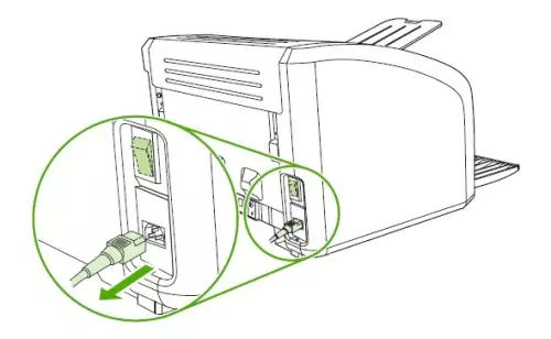
- Turn off the printer, then pull the power wire from the socket and the connector on the device itself.
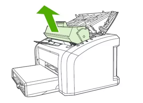
- Wait for the equipment cooling, if before that he actively worked. Raise the top cover and carefully remove the cartridge or cartridges. Sometimes users have difficulty pulling out this particular detail. Detailed information on solving this problem can be found in our other material on the following link.
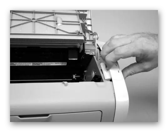
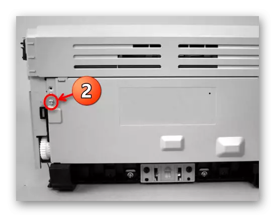
- Unscrew the screw that serves to mount the cover to the case. Please note, in some major models for the mount responds to several screws, you will need to get them all. Only after that, at the bottom, locate the latch and move it until the appropriate sound appears.
- On the side of the top cover there is another latch, remove it with a neat hand movement.
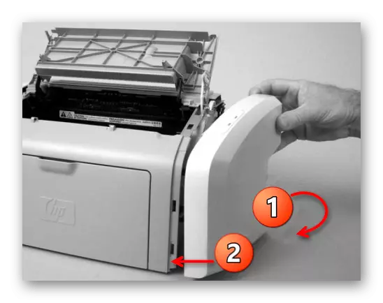
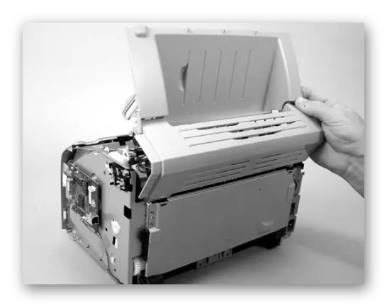
- Perform a small rotation of the back of the cover, then moving forward completely remove it from the housing.
- In case of difficulties with dismantling, consider carefully the presence of additional fasteners, for example, sometimes there is another latch below.
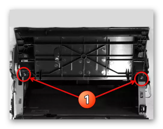
- Lift the top cover and find two identical screws on both sides, which serve for fastening. Unscrew them with a screwdriver.
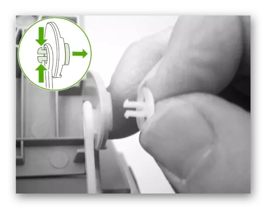
- The opening mechanism is attached using plastic clips. You will need to squeeze two locking protrusions and pull both clips.
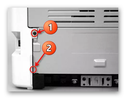
- The back of the device is usually attached only one screw, and it is located on the left.
- After removing the screw, it is enough to raise the panel and remove it from the loops. It should be easy to succumb, since all the screws and clips of the top panel were already extracted.
- Then remove the top cover by lifting it up.
- When you put this panel to place, pay attention to two locks: they should be in their original position, that is, in the appropriate grooves.
- Find a big latch on the left or right side and lower it down, then pull the panel a little over.
- After the lower part is released, continue to pull the element on yourself, while lifting it up a little up to disconnect the remaining snaps.
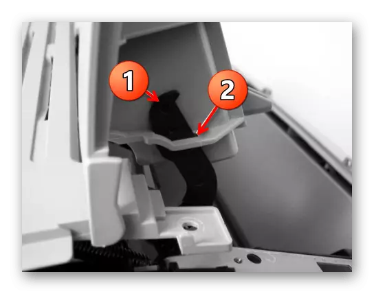
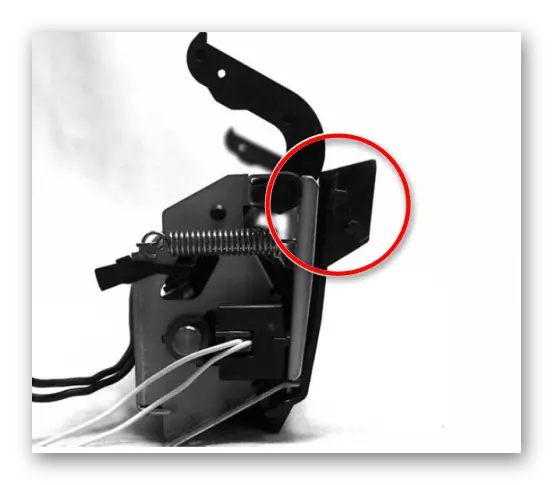
- In the image below you see an example of the location of the latch. With a detailed examination of the device, they can be detected independently and pushing the auxiliary item if you manually disconnect them.
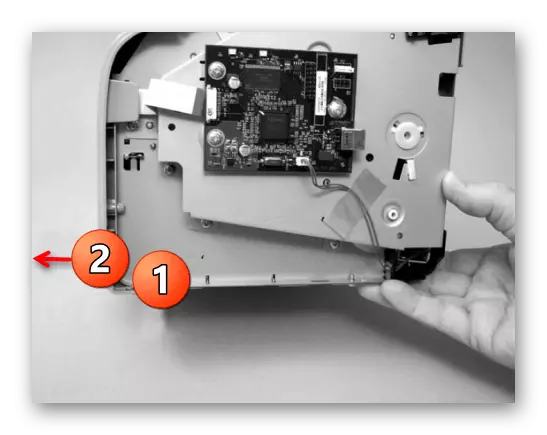
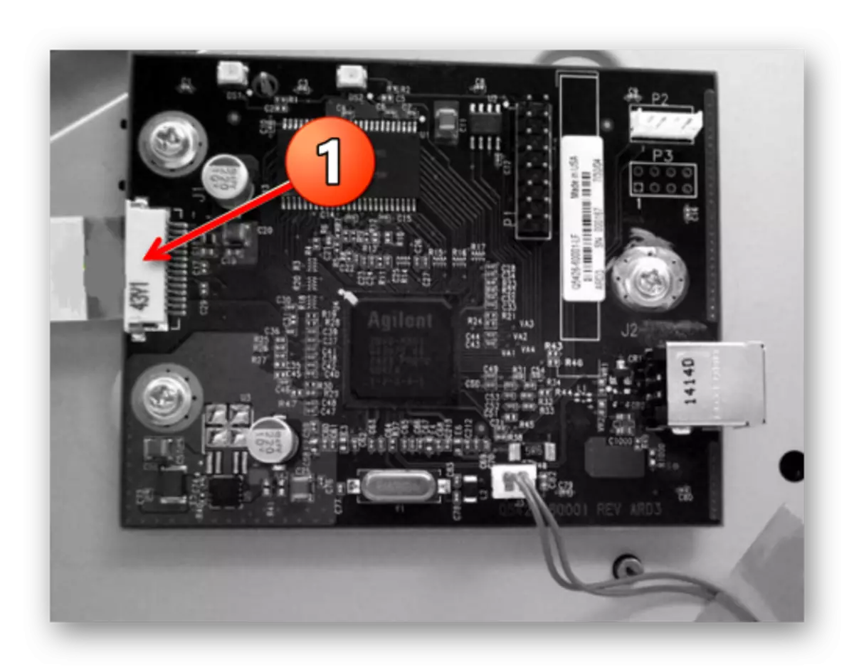
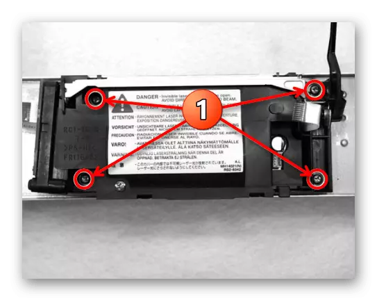
- To begin with, it will be necessary to remove the formatter fee. The formatter fee is the installed microprocessor responsible for the speed of the device. It processes all the information transmitted from the printer to the PC and vice versa. At this board there are many other components - RAM, ROM, other chips, which forms a single chain. The dismantling of the laser block will be possible after disconnecting the loop from the formatter.
- After that, an additional loop is disconnected.
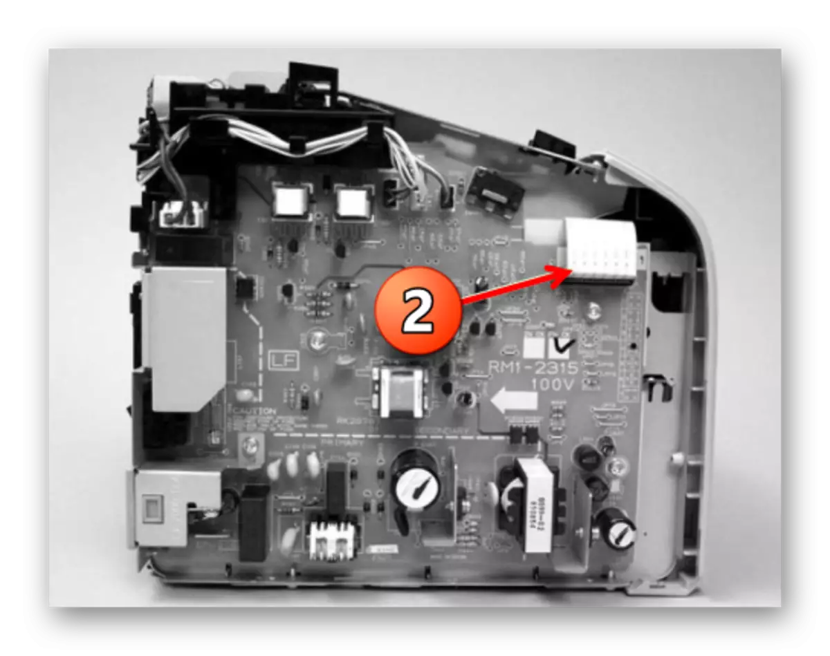
- All screws over the metal lid are unscrewed.
- The cable and loops of the engine control board are disconnected, turn off its mounts and remove it.
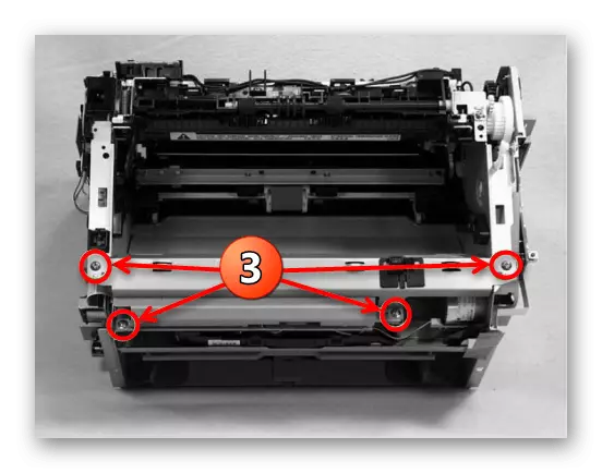
- Then get the last four screws of the laser block and it is considered dismantled.
Step 2: Removing the left and right lid
When examining the printing equipment, you could notice that there are also two identical lids on the sides. Actually, they do not distinguish between the principle of removal:
As mentioned earlier, two side panels are absolutely the same, so you can only do exactly the same operation and with a parallel lid.
Step 3: Top Cover and Rear Panel
Upon completion of the dismantling of the side panels, only the upper and back cover remained. After removing these parts, you can not only explore all the insides, but also unscrew them, freely rotating screws without obstacles in the form of plastic panels.
Step 4: Removing the front panel
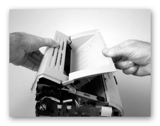
Above you were familiar with the steps to remove the rear, upper and side caps, which together and created one solid fastening for the front panel, so we dismantle it last. Here you need to be attentive because this item is fixed on latches, the number and location of which differ on different models. They must be detected and bend themselves according to the following example:
This removes the protective elements is completed, you have a printer with open internal components. The following steps will be required with extreme caution in order to accidentally do not break the cable or damage the management board boards.
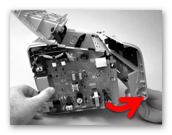
Step 5: Disconnecting Management Board
The control board is responsible for the full performance of the printer. It allows you to configure print properties through a computer, takes electrical signals from the on-board buttons and produces other important actions. It consists of several components, they all form a single system. When breakdown, one of them may experience malfunctions or a complete refusal of it, so the removal must be carried out as little as possible. Disconnect all removable cables, holding the plastic connector, and not for the wires themselves. Usually, on the board, they are all marked with symbols, because of which it is not difficult to find removable elements. Next, unscrew all the boot screws.
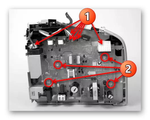
At the rear of the printer there are two more screws holding a chip. In addition, there is a high-voltage wire, which also needs to be disconnected.
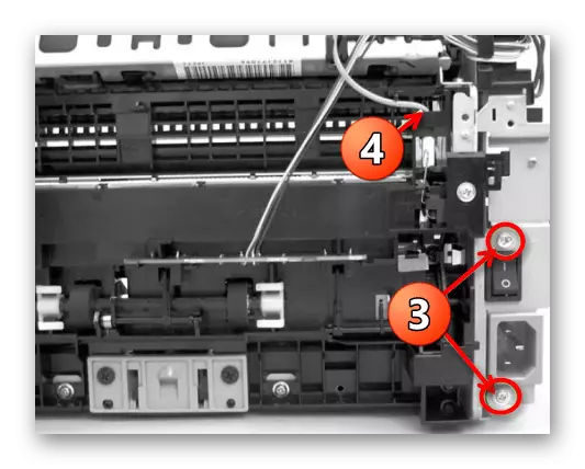
After that, the board can be carefully getting and put on the fabric or foam rubber to avoid surface scuffs. Transportation of the board to the service center only in a protective box and a film in order to avoid any blows and breakdowns at a random drop.
Step 6: Dismantling the thermal shrinking unit
Now you reached the thermal shrinking site. This part performs the role of a furnace and baked ink on high temperatures on high temperatures. Sometimes it fails, as evidenced by the smeared ink on finished sheets. If you need to remove and replace the node, simply unscrew the fastening screws, usually the number of which does not exceed three pieces.
When installing a new node, consider the location of the plastic tag. It is important to perform all actions without damaging this element, otherwise you will have to acquire a new component, and this will be in disrepair.
Step 7: Transportation Node
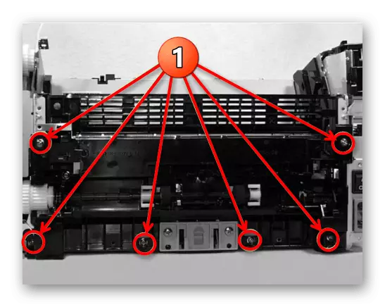
There are several different variants of paper transportation nodes. We will not go into the technical details of each of them, but only tell about the way to dismantle this system. It lies in the simple unscrewing of all fixings. Usually they are located all over the perimeter of the printer and stand out among other screws in their size.
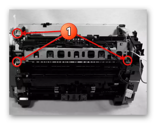
Step 8: Laser Block
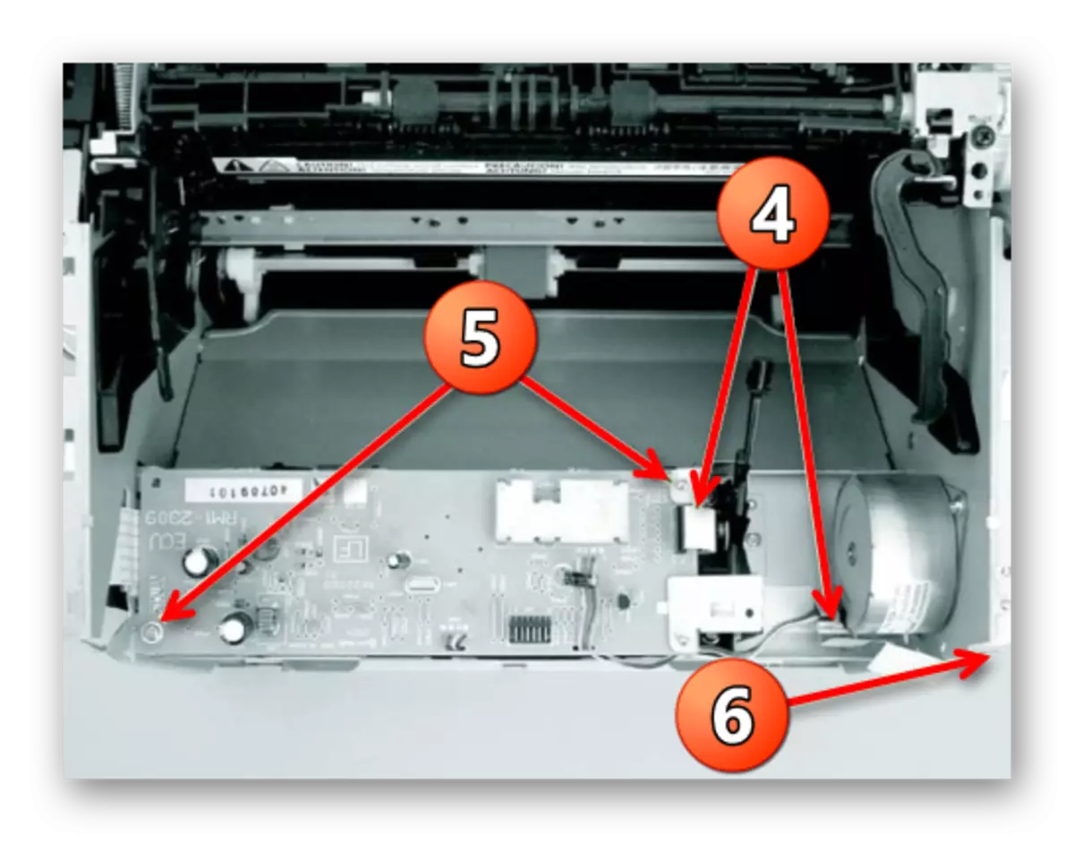
The last step of disassembling printing equipment from Canon is the removal of the laser block in the case of laser devices. The component of the inkjet printer is practically no different, but it has its own characteristics, as you can read in the instructions. As for the laser board, its removal is done like this:
Now the Canon printer is considered to be completely disassembled, you can send the necessary parts to the service center or to produce them with independent diagnostics. The assembly is carried out in the same way in the reverse order. Do not forget to fasten all the screws to your own places, do not lose them and do not confuse, so that during the work it does not disappear or did any part of the device damaged.
See also:
Cleaning Canon Printers
How to configure Canon printer