

Multilia is one of the standard built-in AutoCAD software tools, which, until recently, was located in the main ribbon with all other functions. However, the developers considered that it would be better to remove the multilia and all its components from the main panel by filling out the released space with more useful buttons. However, now many beginners and professional users still actively use this feature when drawing up drawings. Therefore, today we want to talk about this concept, show how to return the line on the ribbon and demonstrate an example of creating / editing the elements.
Multilia function in AutoCAD
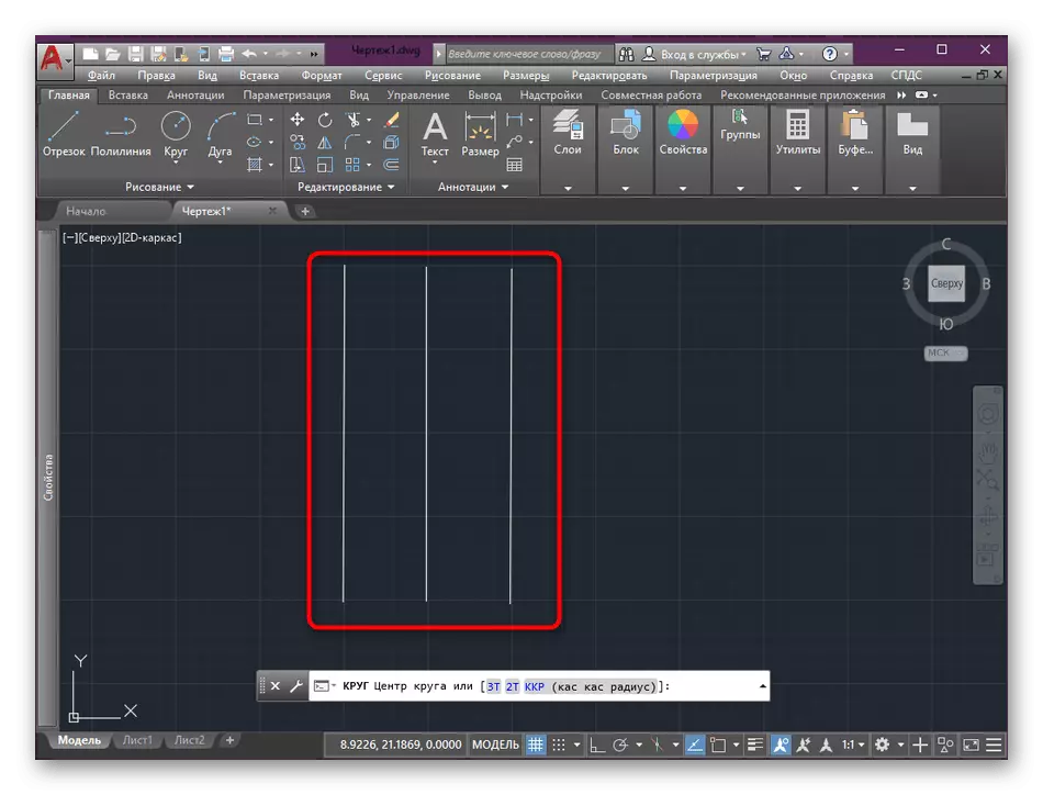
Multilinia is called a totality of lines located in parallel to each other relative to the guide. The role of the guide is the so-called polyline, near which the user and draws the remaining segments with a certain displacement. This feature is actively used in a wide variety of projects and drawings, for example, when designing walls or roads. At the following image, you see an example of this element.
Interaction with Multilia in AutoCAD
Above, we briefly disassembled the very concept of the object under consideration today. Now it's time to talk about its use. Conditionally divide the contents of the material into several simple instructions that will help in mastering the function and allow you to quickly learn how to control multilinia.Return to the main ribbon
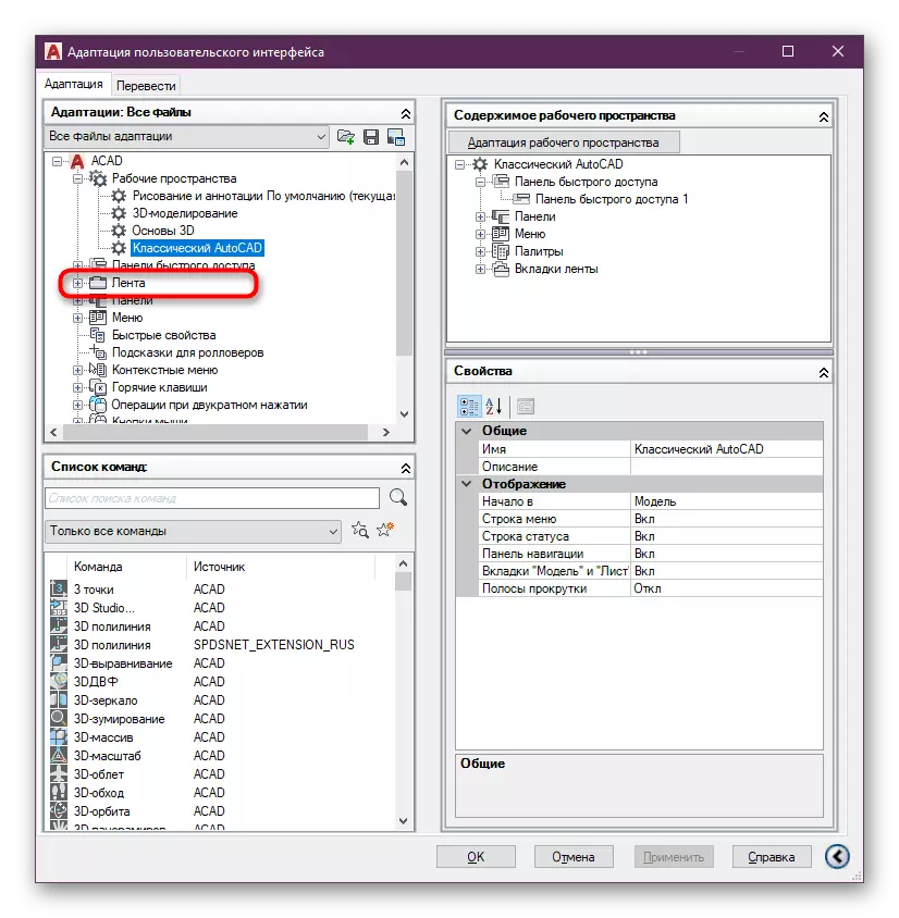
As already mentioned earlier, Multilia was removed from the main ribbon. Therefore, it is worth starting with the return of all related components to the main panel, if, of course, you are going on an ongoing basis to use them. The whole procedure is to edit the user interface, which looks like this:
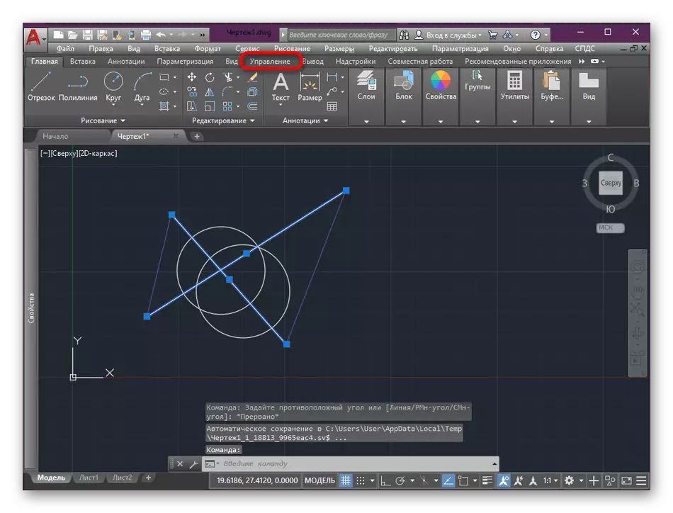
- Run the autocadus and go to the Management tab.
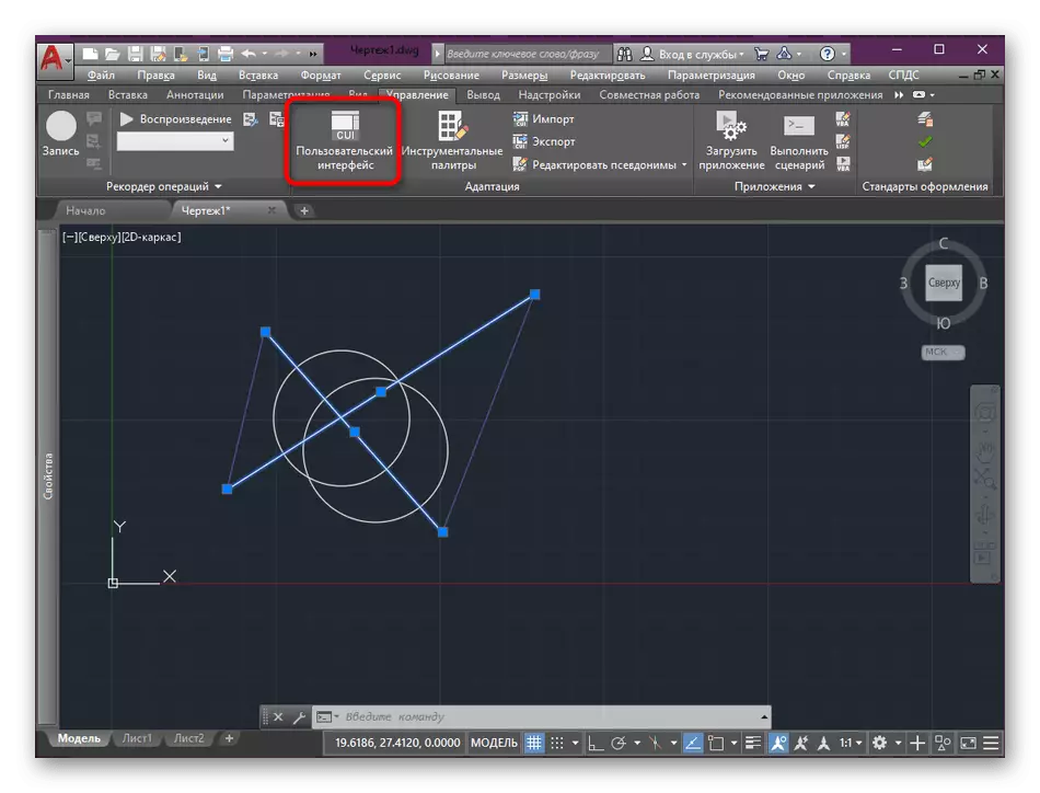
- Here, click on the "User Interface" button.
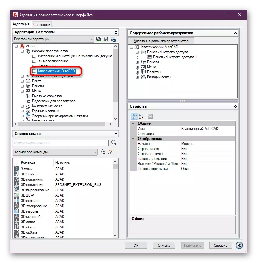
- Make sure that the workspace you need is activated.
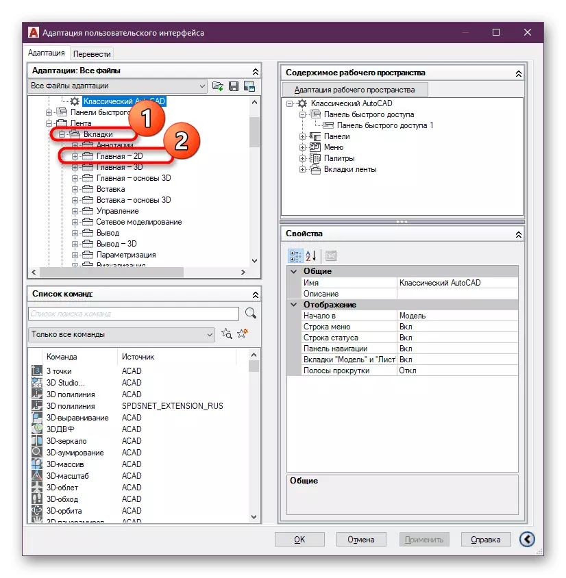
- Then expand the list called "Tape".
- Open "tabs" and select "Home - 2D".
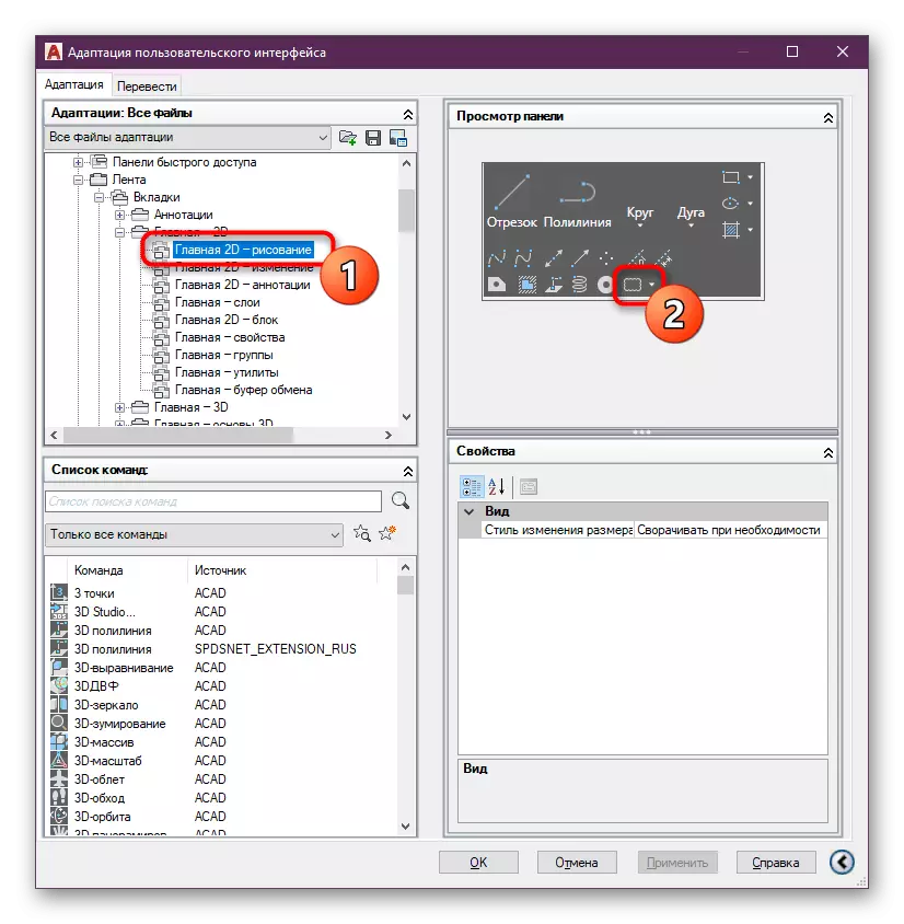
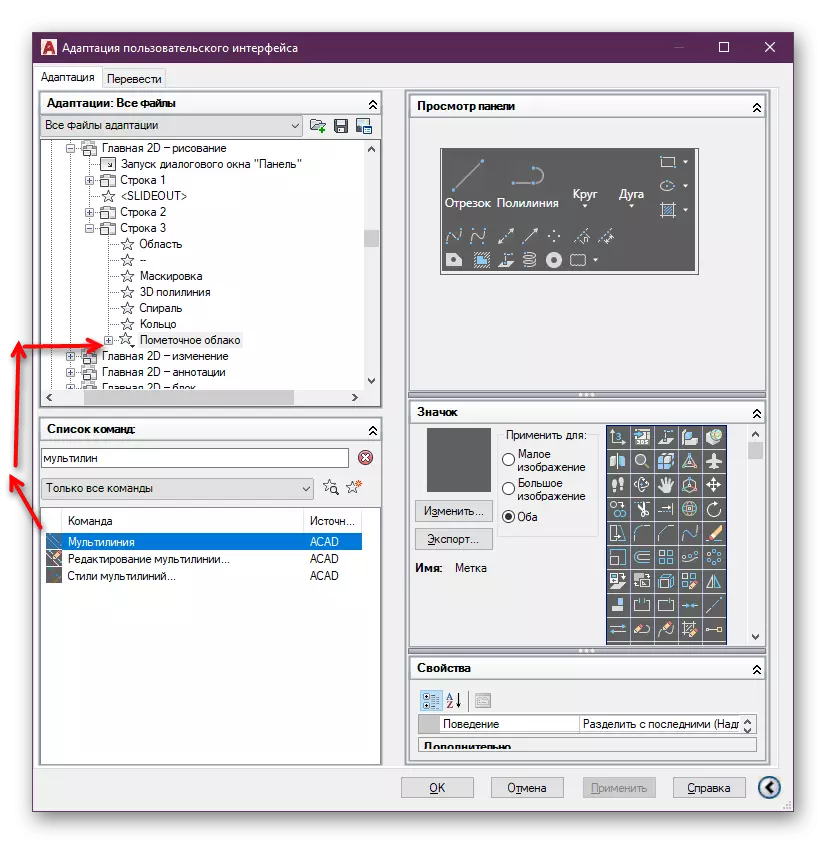
- It is best to place multilia in the "Drawing" section, since it is this action that it performs. Highlight this directory and in the panel browse window, click on the last button.
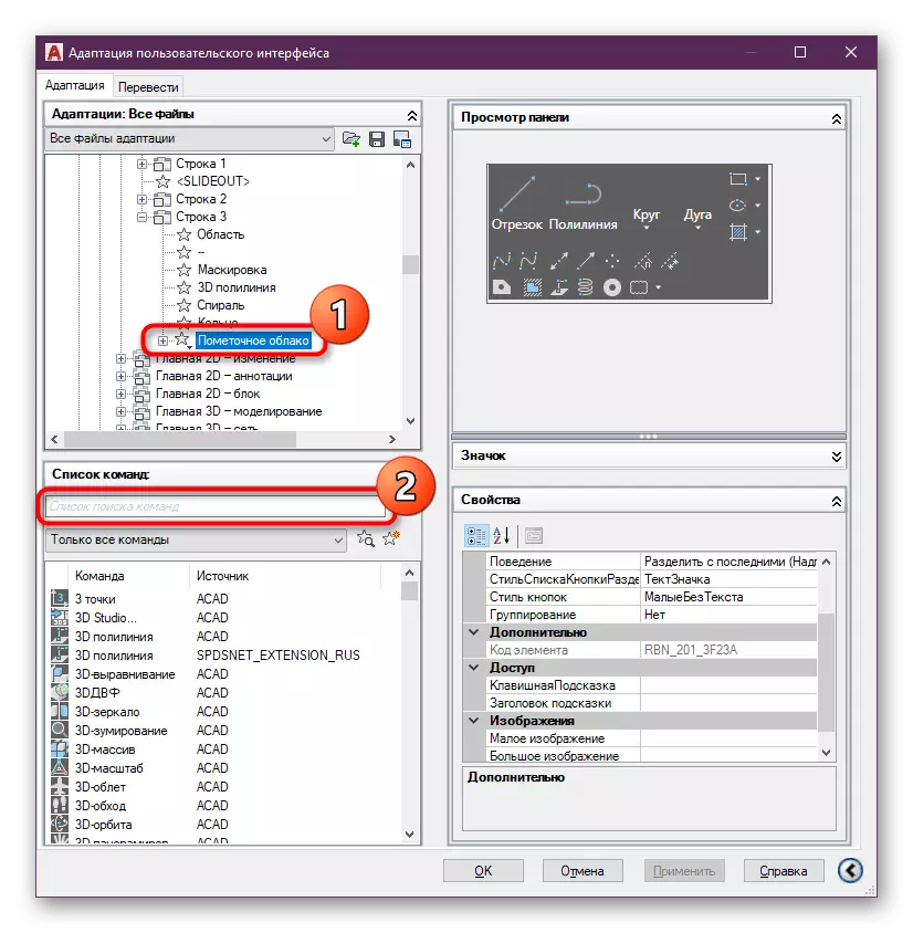
- It will be automatically moving to the last row. Now you should find the Multilia buttons. To do this, in the list of commands, start typing name.
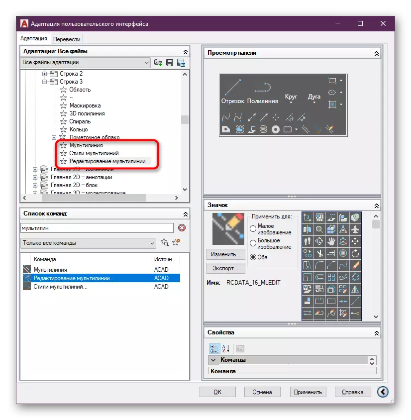
- You will need only two commands from the "Multilia" list and "Multi-Multi Styles". The editing of multiline is easier to exercise a little different method, which we will talk about, so adding this command is not at all necessary. Hold the string with the left mouse button, boot the object outside the window, then lift up and place the string to the latest tool. Such actions are needed so that the list of rows accidentally does not flew down when the cursor is hovering. Then you will have to seek the open directory.
- Do this and do the remaining teams.
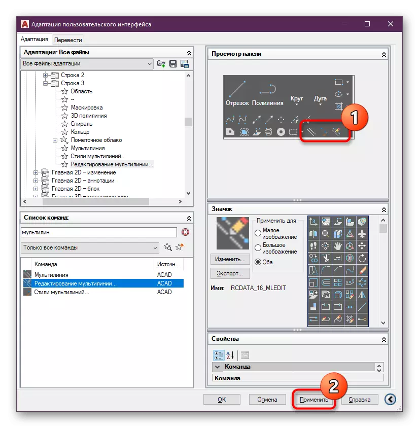
- In the Preview window of the panels, you will see that the new buttons have been successfully added. Upon completion, click on "Apply" and boldly close this window.
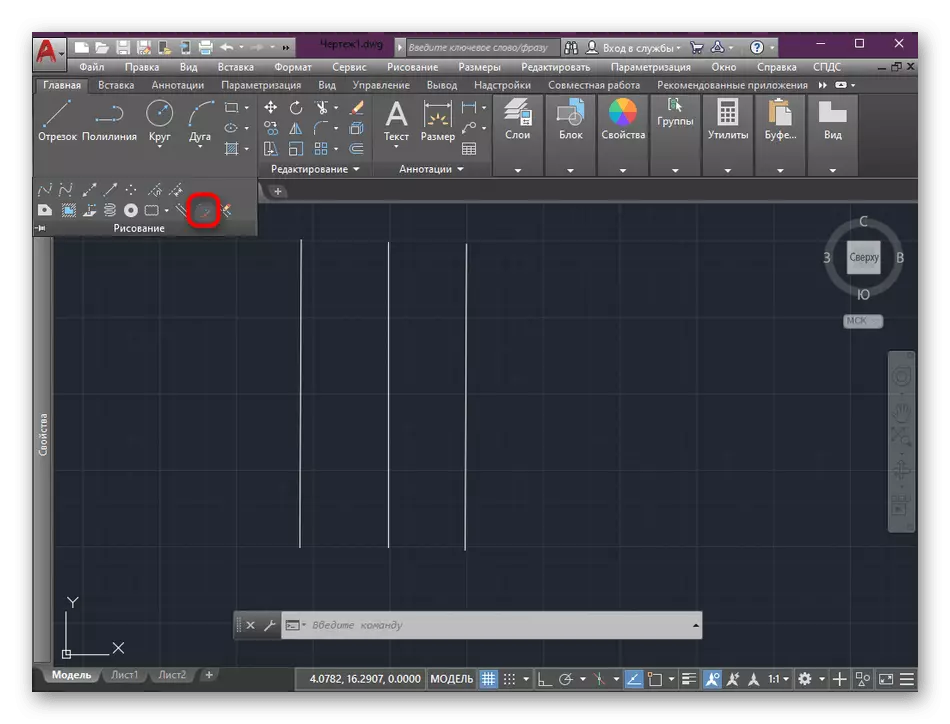
- Move again to the "Home" section, where in the "Drawing" category, locate Multi Tools.
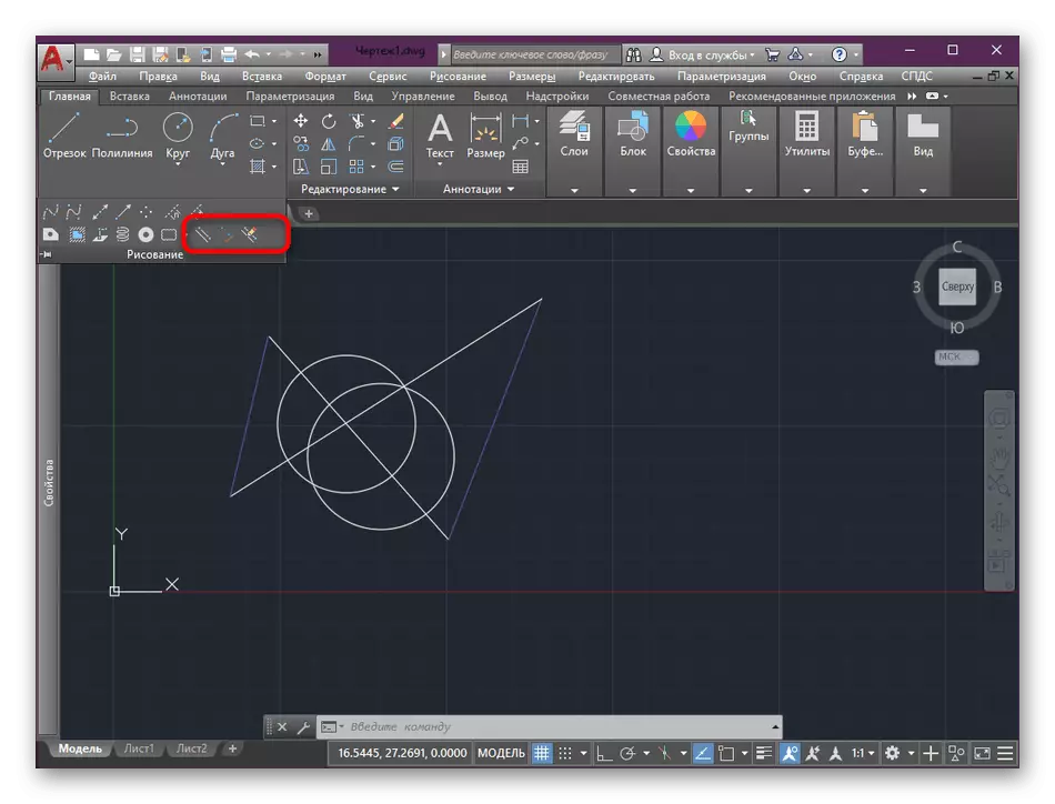
As you can see, all actions are performed literally in a few minutes. Now you can manage the lines much faster, edit them and change properties.
Creating multilia
The main process performed with the tool under consideration is precisely the creation of multilia relative to the existing guide. To do this, it should already be created, and the dimensions must also be known. We take a small project of a double wall for an example, and you, pushing out from what they saw, embody the operation in your drawing.
- In the screenshot, the guides are visible for future multilios. In your case, it can be absolutely any layout that will help in creating the following elements.
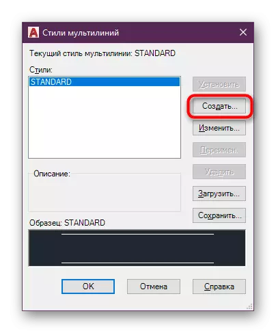
- In the "Drawing" section, click on "Multi-Multi Styles" to go to the creation.
- Create a new style by clicking on the corresponding button.
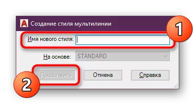
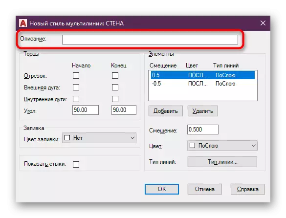
- Ask him the name. It should be borne in mind that it is impossible to use spaces. It is best to share words by the lower underscore. After setting the name, click on "Continue".
- In case of need, specify the description of the style, as well as add ends and fill. This is not the most important effect, so it will not stop on it, but we will immediately move on to the items.
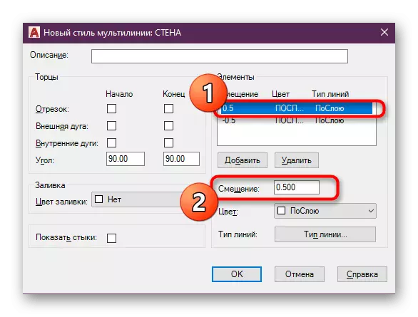
- Now you need to enter a shift in millimeters. Negative value goes left, and positive is right. Here, repel from the existing size of the drawing.
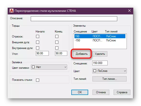
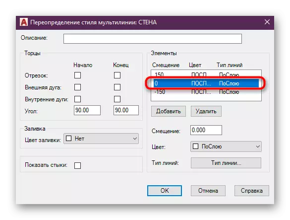
- If required, add the required number of displacement elements.
- However, do not forget that for each line you need to set the appropriate displacement size.
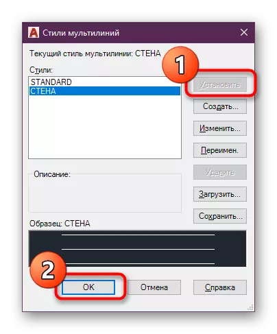
- At the end of the configuration, exit the setup window, select Style, click on "Set" and then on "OK".
You can create such styles to create an unlimited quantity by setting different displacement values and adding the required items. In the "Multi-Multi-Style" section, the preview window is located at the bottom, so it will be enough to find a suitable style at the right moment. Now let's talk about how to apply the style to the drawing.
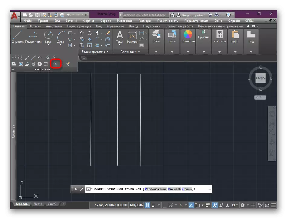
- Expand the "Drawing" section and select the "Multilia" tool there, which we have previously added by editing the tape.
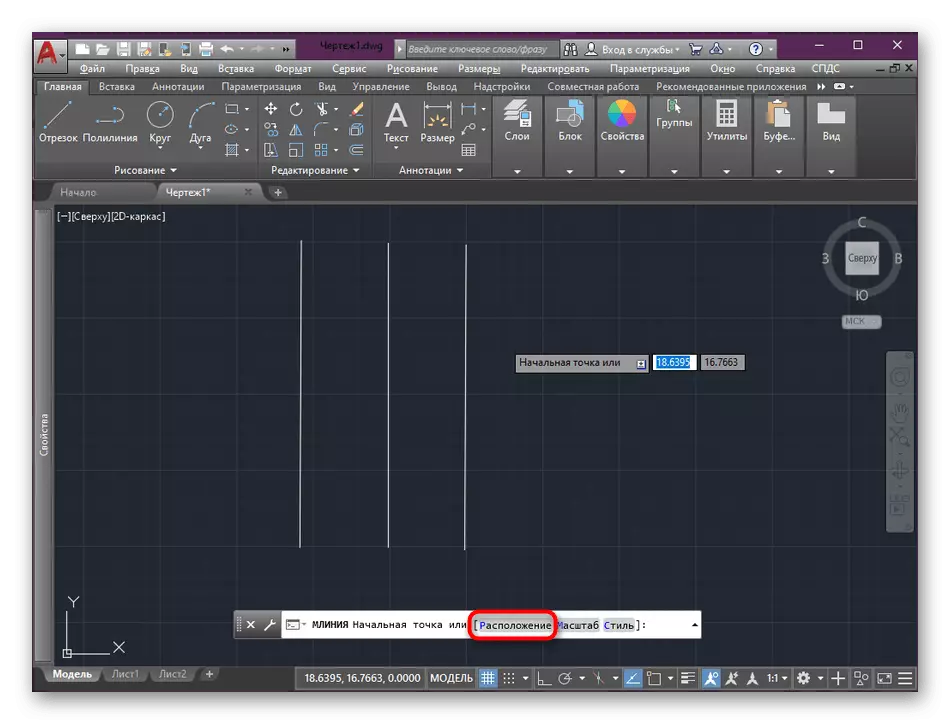
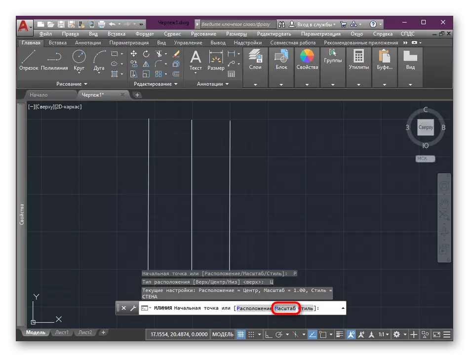
- To start, set the main location by clicking on the inscription on the command line.
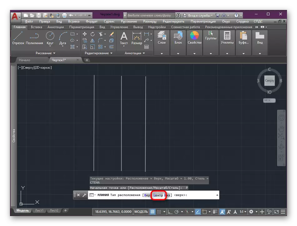
- We will be repelled from the center, therefore we will specify this type.
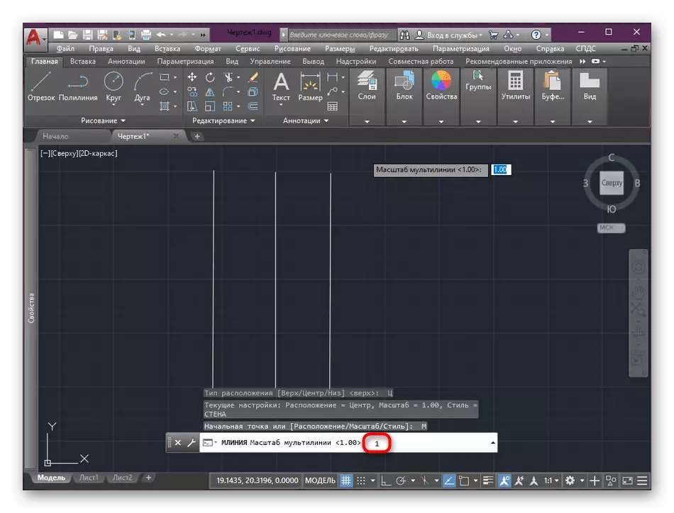
- Next, it is important to set the correct scale.
- In most cases, it is 1: 1, so you write the number 1 in the console.
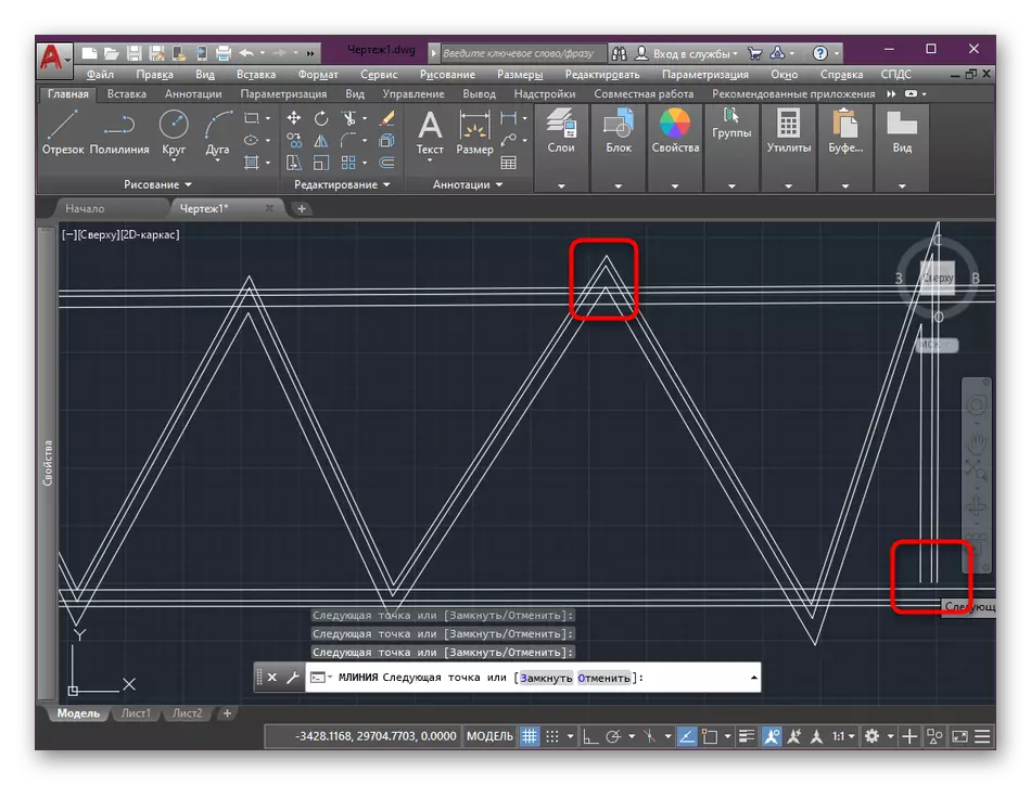
- Start drawing multilia, adding the required number of points.
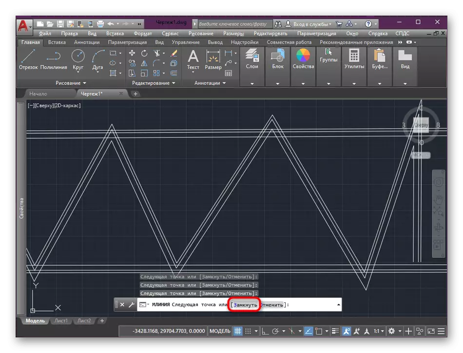
- When you come to an end, you will need to close the drawing. You can do it yourself and on your own, but it is best to use an automatic function that will perform everything as correct as possible.
In the same way, the desired number of the most diverse multilios is created in the drawing using different styles and location options. The instruction is above called only to demonstrate the foundations of creating on the most accessible example, because the circle of using such elements is very wide, and the potential is unlimited.
Editing Multilia
Previously, we already taped the theme editing multilios when the tools of this function were added to the tape. As it was said, switching to changing the choice of the corresponding button is inconvenient. Everything is much easier.
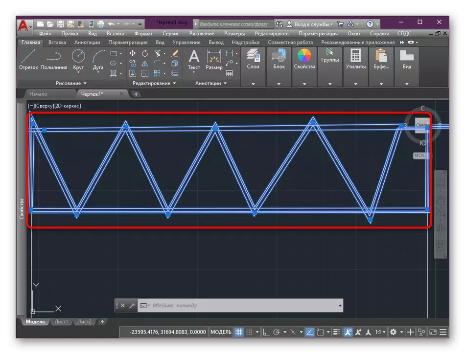
- Twice click on the left mouse button on the available Multilia on the workspace.
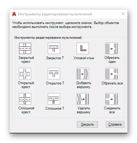
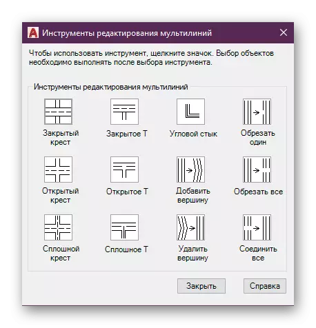
- The editing tool window will open, where several examples of the location change can be seen, such as the "angular joint" or connection through "closed T". Select the option that is required for the current change.
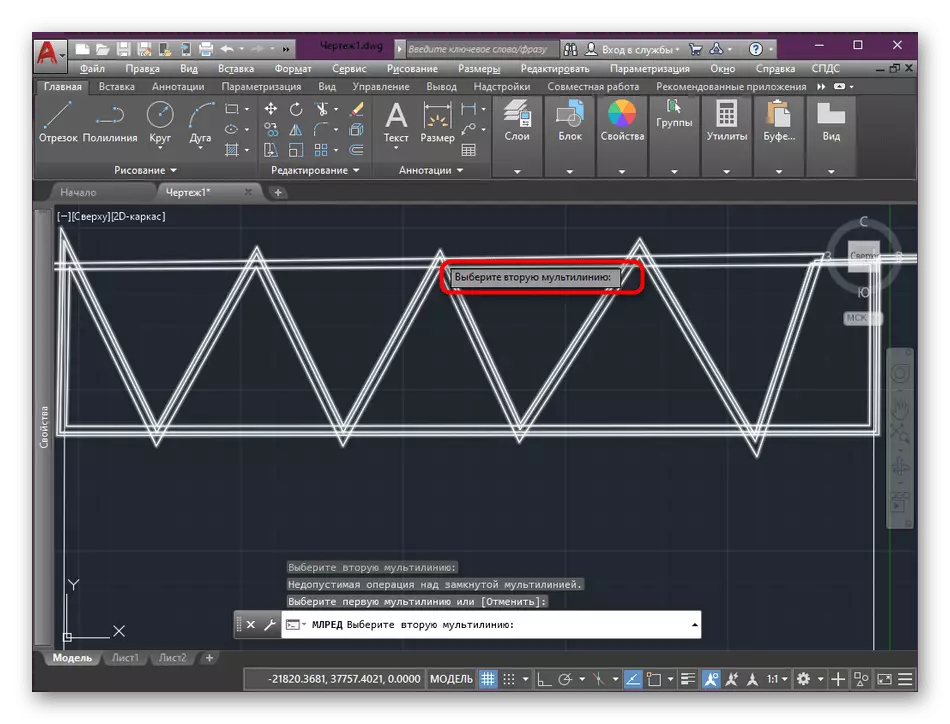
- Mark two multilia in the drawing so that the settings automatically entered into force.
- It also uses absolutely all tools for editing joints, angles and connections.
Annotative hatchovka
The last topic we want to affect under today's material is an annotative hatch. It would seem that the hatching does not apply to the topic of multilios, however, the video created is exactly the type of this element. Some users specifically make multilia to create a hatching, although it is far from always comfortable. It is easier to make it as shown below.
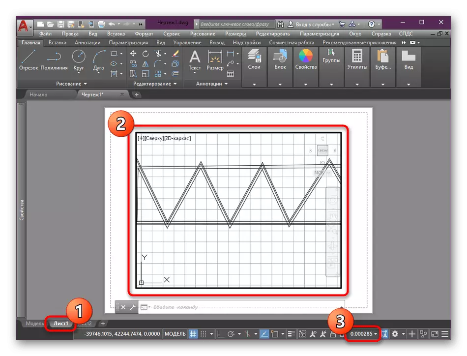
- To begin with, move in the species screen and adjust the suitable scale so that the shading is displayed correctly at any view. To do this, just increase or reduce the sheet to the optimal value, and then look at what scale is shown to the right below.
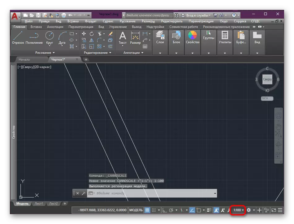
- Now in the main workspace, select the scale as close to the previously seen.
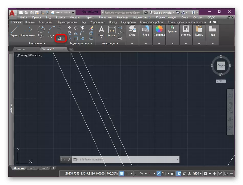
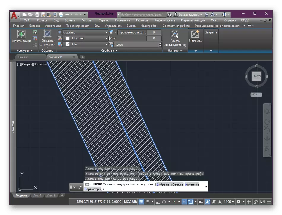
- Click on the hatching tool, which is in the "Drawing" section.
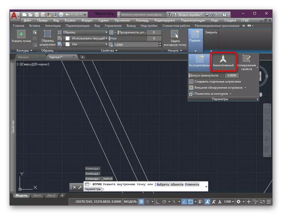
- Expand the "Parameters" section and go to "Annotative" mode.
- Click on the area within two parallel lines to automatically fill them with a hatching.
Similarly, it will remain fill in all the areas of the drawing, and you can be sure that when the project is changed, no problems with the mapping of hatching will occur.
Lines in AutoCAD are the main objects that are present absolutely in all drawings. Because each user faces the need to create, edit and associate. We encourage beginners to familiarize yourself with some materials, where the principles of basic interaction with lines are clearly shown.
Read more:
How to add line type in AutoCAD
How to combine lines in AutoCAD
How to make a dotted line in AutoCAD
How to trim the line in autocad
Today you were familiar with the principles of using Multilia in the AutoCAD program. It will help in the performance of many details of the drawing of almost any direction. If you are interested in performing other actions in this software, we advise you to learn the training material on this topic by clicking on the link below.
Read more: How to use the AUTOCAD program