

The main elements of the drawing in AutoCAD usually consist of segments and polylines. Of these, more complex structures are created combined into blocks or arranged separately. Sometimes the user during the interaction with the project faces the need to transform a group of segments into one polyline to simplify work with them. You can perform the set target in two different ways. They both conclude in the use of built-in autocardic functions, but the actions algorithm will be slightly different.
Differences between polyline and segments
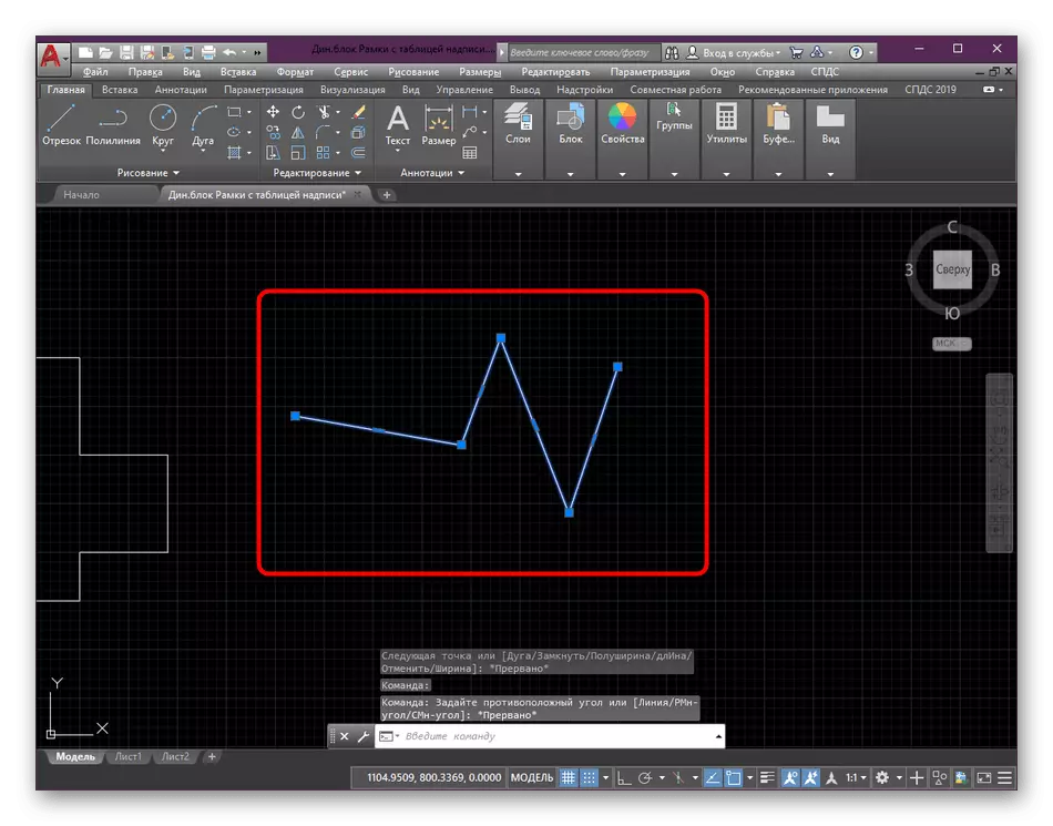
First, let's talk about the most important differences in the polyline and segments, so that novice users do not have any questions about this and immediately it became clear why many are still carrying out such conversion. Starting with a segment: a similar line is an element of direct, limited points at both ends. Built in AutoCAD tool "Cut" allows you to add such lines to the drawing card in cyclic order, where the first point of the new segment is created on the final previous one. The entire catch of such a structure lies in the fact that at least an object looks like one thing, but each segment is edited, moves and removed separately. When attempting to add hatching or other auxiliary components, errors may be observed. For example, the fill will not pass successfully, since it turns out that the points are not completely closed. It is because of such nuances and are created by Polyline.

As for the polyline, its principle of creating is almost similar to what you see when adding a segment. However, in this case, all points are closed into a single whole, and the object itself is a block. If you edit one of the points of the polyline, the neighboring is also affected, which allows you to create unique curvatures and similar effects. With the help of the "Dismouncing" function, the "explosion" of the polyline is performed, and as a result, each component is a separate segment.
The above instruction is one of the aspects used in drawing drawings in AutoCAD. If you are not familiar with this process, we advise you to read a special learning material on this topic on our website by clicking on the link below. There you will find detailed instructions on interaction with basic functions and capabilities.
Read more: Drawing of two-dimensional objects in AutoCAD
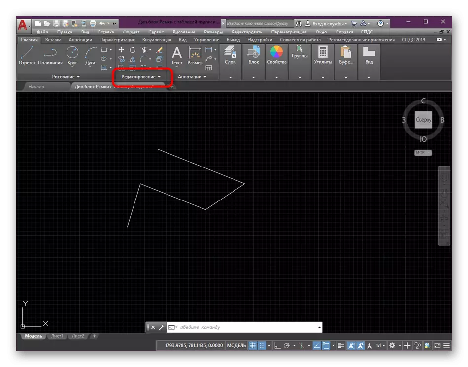
Method 2: Connect tool
In some cases, the exhaustable example will seem the optimal option for creating a polyline from segments, however, there is a method that allows you to perform this procedure a little faster. The principle of its action lies in the connection of the existing lines, and the entire operation looks like this:
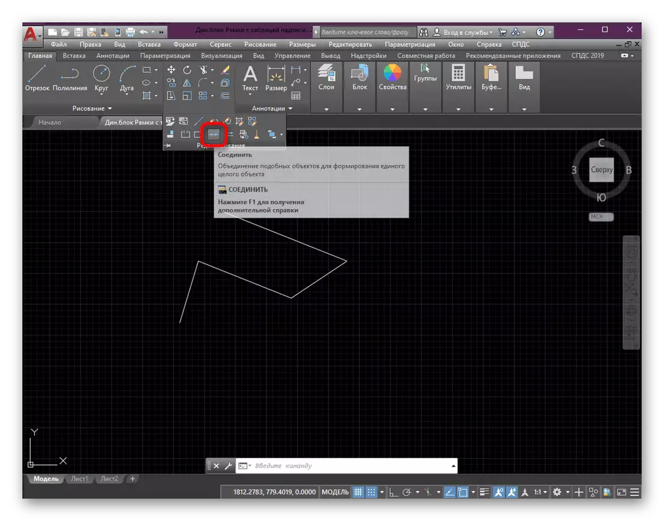
- Expand all elements of the Editing section again.
- Choose "Connect" there.
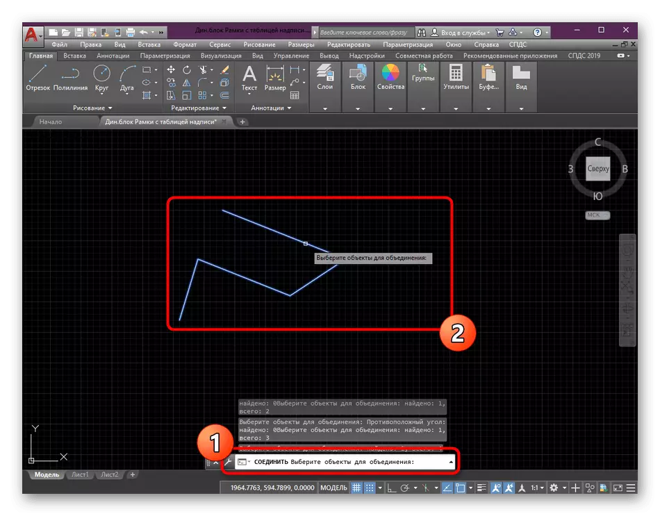
- Using the left click on the mouse, select all objects for further association.
- Press the Enter key to apply the tool action.
- The same can be done with three-dimensional segments, it should be borne in mind that 3D polylines will be obtained as a result of the connection.


As for further editing blocks, objects and primitives, this is carried out only if necessary while working on the drawing. If you are interested in such training instructions, we advise you to get acquainted with other similar materials by reading another lesson on our website by reference Next.
Read more: Using AutoCAD Program