
On the front panel of the system unit are the buttons that are required to turn on / off / restart PCs, hard drives, light indicators and a drive, if the last two are provided with the design. The process of connecting to the motherboard front of the system unit is a mandatory procedure.
Important information
To begin with, learn the appearance of each free connector on the system board, as well as cables to connect the front panel components. When connected, it is important to comply with a certain order, because If you connect one or another item in a non-order, then it can work incorrectly, not to work at all or disrupt the operation of the entire system.Therefore, it is important to study the location of all elements in advance. It will be very good if there is an instruction or other paper to the maternal card, which explains the scene of connecting certain components to the board. Even if the documentation for the motherboard on another, different from the Russian language, do not throw it out.
Remember the location and the name of all elements is easy, because They have a certain appearance and marked. It should be remembered that the instruction given in the article is common, so the location of some components on your maternal card may be a little different.
Stage 1: Connect buttons and indicators
This stage is vital for the computer, therefore it is required to be performed first. Before starting work, it is recommended to turn off the computer from the network to avoid a sudden voltage jump.
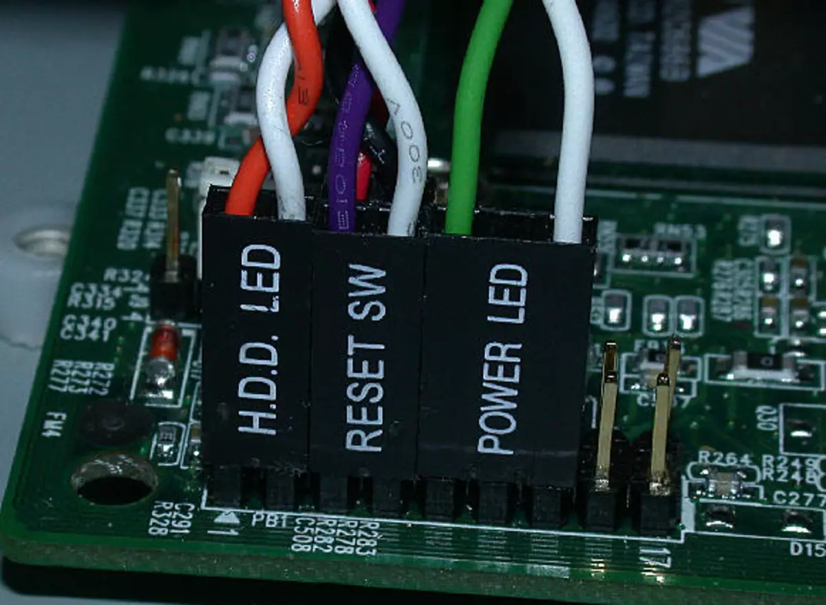
On the motherboard highlighted a special unit, which is intended only for alignment of wires of indicators and buttons. It is called "Front Panel", "Panel" or "F-Panel". On all motherboards, it is signed and located at the bottom, closer to the alleged location of the front panel.
Consider connecting wires in more detail:
- Red wire - Designed to connect the Turn on / off button;
- The yellow wire is connected to the computer's reset button;
- The blue cable is responsible for one of the indicators of the system status, which is usually lit when the PC is rebooting (there are no such cases on some models);
- Green cable is designed to connect a motherboard with a computer power indicator.
- White cable is needed to connect power.
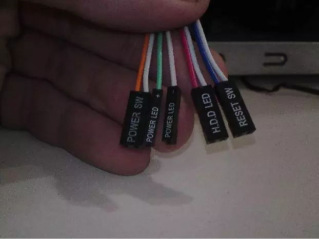
Sometimes red and yellow wires "change" with their functions, which can be confused, so it is desirable to study the instructions before starting work.
Places to connect each wire are usually designated by the appropriate color or have a special identifier that is prescribed either on the cable itself or in the instructions. If you do not know where to connect one or another wire, connect it "at random", because Then you can still reconnect.
To check the correctness of the connection of cables, connect the computer to the network and try to enable using the button on the housing. If the computer turned on and all indicators are burning - it means that you all connected everything. If not, then turn off the computer again and try to change the wires in some places, you may just install the cable not on that connector.
Stage 2: Connecting the remaining components
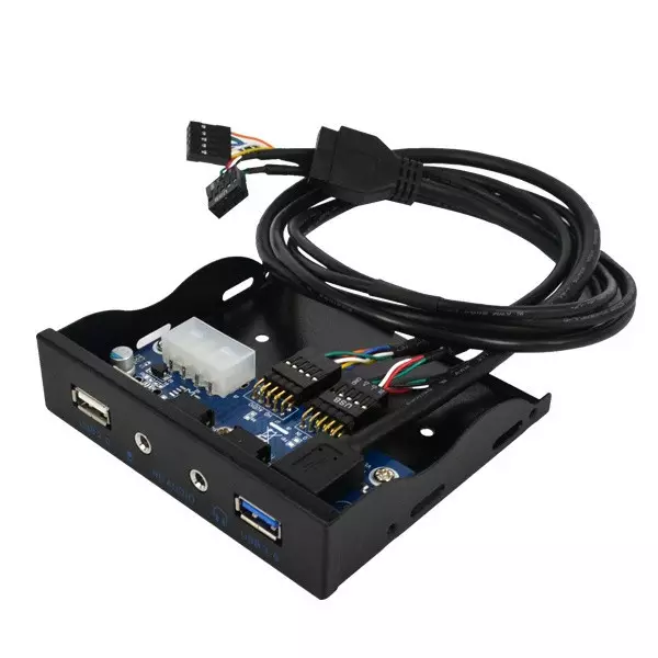
At this stage, you must connect the connector for USB and the system block speaker. The design of some enclosures does not provide data to the elements on the front panel, so if you did not find any outputs for USB on the case, you can skip this step.
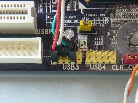
Places to connect connectors are not far from the slot to connect buttons and indicators. They also carry certain names - F_USB1 (the most common option). It should be borne in mind that these places can be more than one on the motherboard, but you can connect to anyone. Cables also have appropriate signatures - USB and HD Audio.
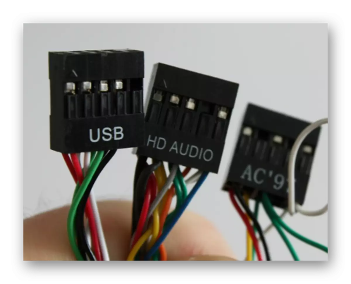
Connecting a USB-input Wire Looks like this: Take the cable with the "USB" or "F_USB" inscription and connect it to one of the blue connections on the motherboard. If you have a USB 3.0 version, you will have to read the instructions, because In this case, you will have to connect the cable only to one of the connectors, otherwise the computer will incorrectly work with USB drives.
Similarly, you need to connect the HD Audio sound cable. The connector under it looks almost the same as under USB outputs, but has another color and is called either AAFP or AC90. It is usually located next to the USB connection site. On the motherboard he is only one.
Connect the front panel elements to the motherboard is easy. If you allow something error, then this can be fixed at any time. However, if you do not fix it, the computer can work incorrectly.